Device and method for reconstruction of osseous skeletal defects

a technology for osseous skeletal defects and medical devices, applied in the direction of prosthesis, ligaments, shoulder joints, etc., can solve the problem of not providing means for reconstituting normal bony structures, and achieve the effect of immediate stabilization of the extremity

Active Publication Date: 2012-05-29
JAMALI AMIR A
View PDF36 Cites 24 Cited by
  • Summary
  • Abstract
  • Description
  • Claims
  • Application Information

AI Technical Summary

Benefits of technology

[0017]The present invention is a method and device that allows immediate stabilization of the extremity with a press-fit or cemented prosthesis fixed to the native bone. Surrounding the prosthesis is a potential space enclosed by a flexible member. The potential space is filled with bone graft materials such as cancellous bone chips, bone morphogenic proteins, etc. The factor distinguishing the present invention is that the circumferential cavitary space (i.e., hollow space) around the implant which allows the reformation of an entire bony network. This is because the cavitary space is a single, unitary potential space, which when filled with a volume of osteoconductive material creates a monolithic or single volume that closely matches normal bony architecture, with continuous and contiguous material around a portion of both the implantable portion of the apparatus and the proximal prosthetic portion of the apparatus. Stated another way, the cavitary (hollow) space is not interrupted by any prosthetic structure that divides the volume of the cavitary space into discrete and separate volumes. This features is different from and superior to that seen with allograft prosthetic composites which contain a structural, cortical allograft. It distinguishes over prior art devices that form a plurality of cavitary spaces around an implant element but which do not provide means to reconstitute normal bony architecture. In the present invention, as the bed of particulate bone graft matures, it is gradually exposed to increasing stresses to encourage remodeling and maturation into normal bony architecture.

Problems solved by technology

It distinguishes over prior art devices that form a plurality of cavitary spaces around an implant element but which do not provide means to reconstitute normal bony architecture.

Method used


Image

  • Device and method for reconstruction of osseous skeletal defects
  • Device and method for reconstruction of osseous skeletal defects
  • Device and method for reconstruction of osseous skeletal defects

Examples


example 1

Femoral Resection

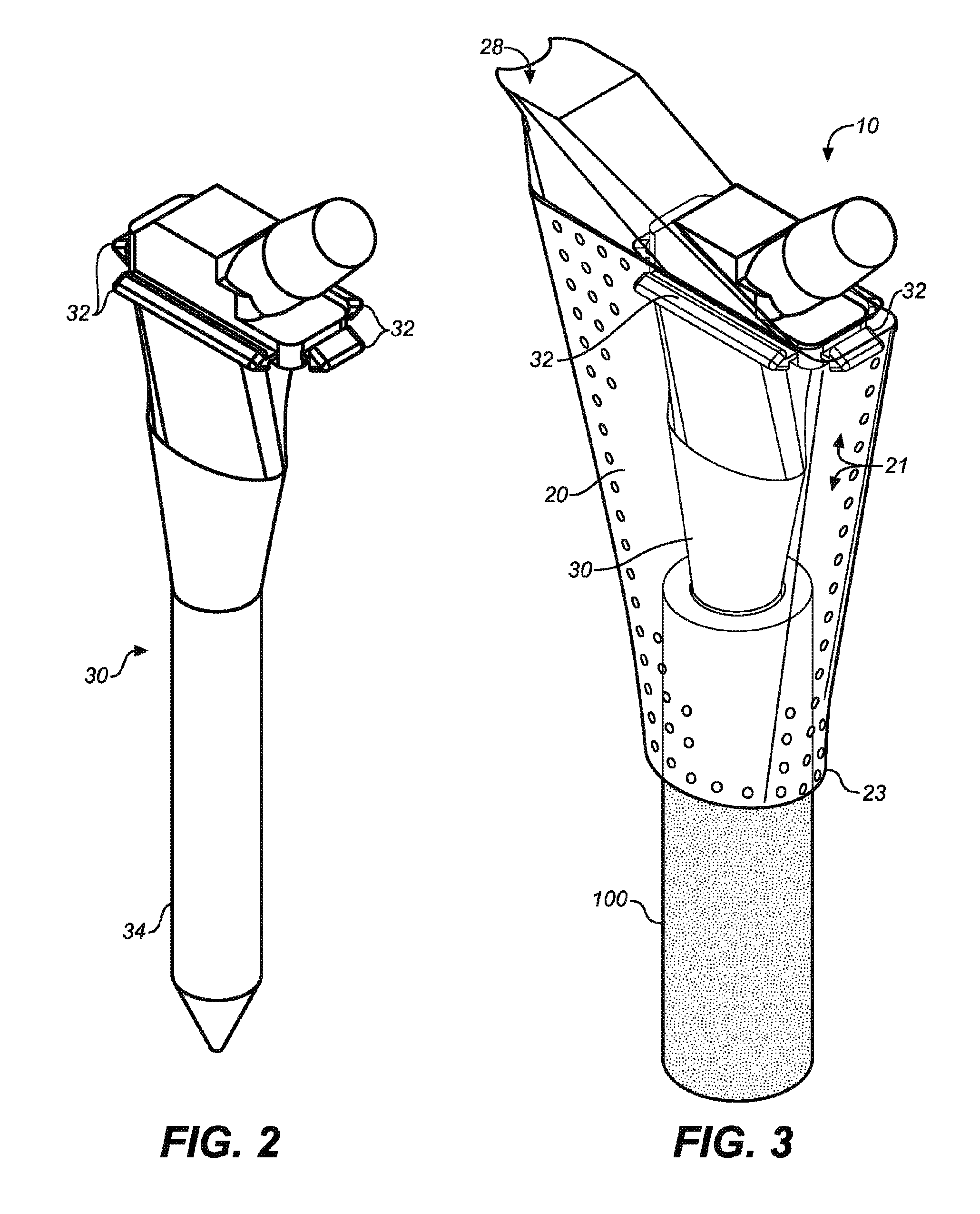
[0067]Referring next to FIGS. 2 and 3, the present invention is utilized in resection of a proximal femoral osteosarcoma in a 15 year old male. FIG. 2 illustrates a femoral prosthesis 30 of the present invention, and FIG. 3 illustrates an implantable device 10 comprising the femoral prosthesis 30 surrounded by a flexible member 20. The implantable device 10 is used to reconstruct the proximal femur of a patient (not shown) in a five-step process. This process is adaptable for use, as will be evident to those of skill in the art, within any of the large joints including the hip, knee, shoulder, elbow, and ankle.

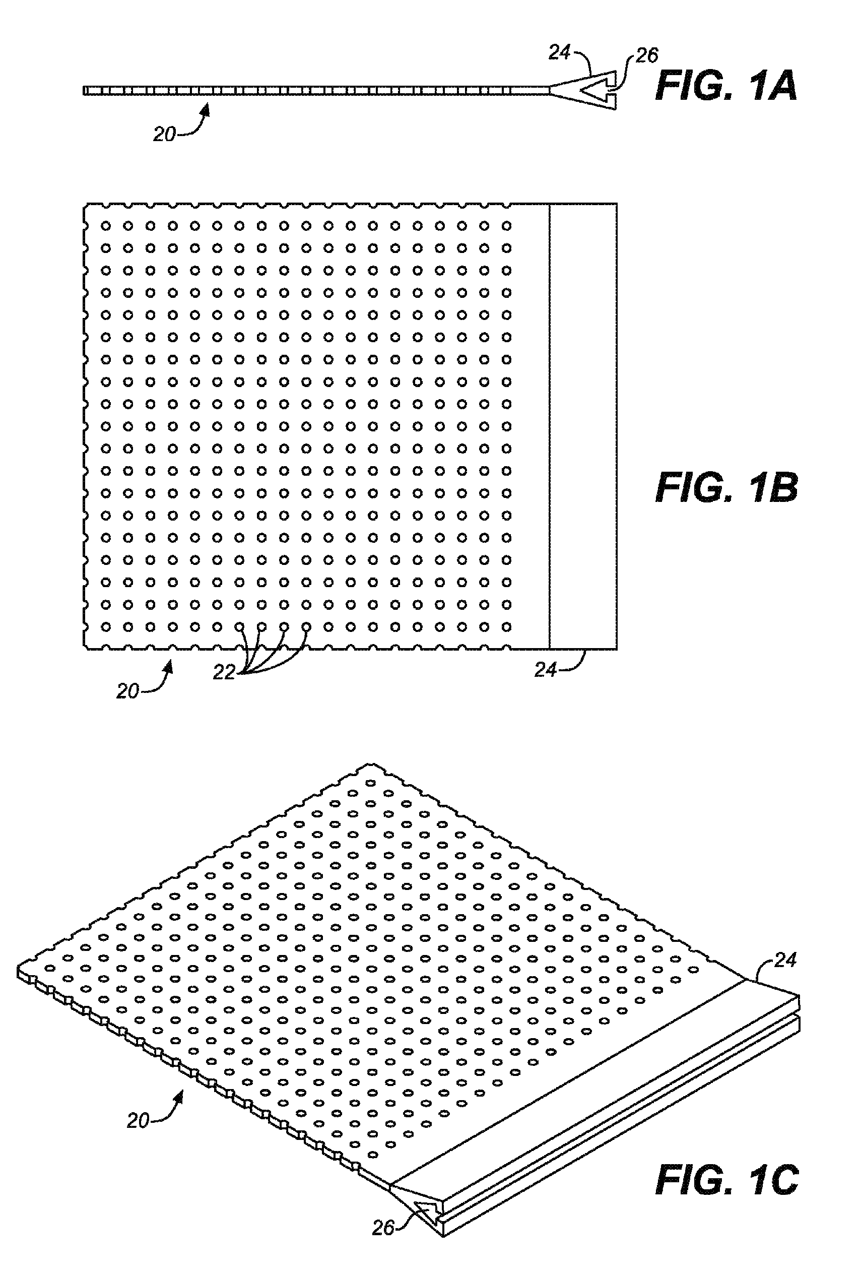
[0068]First, a prosthesis 30 is selected for use, with consideration given to the appropriate height and diameter of the stem 34 in order to achieve adequate fixation, leg length restoration, and soft tissue tension in the extremity. The prosthesis 30 is provided with one or more attachment members 32. In this instance, rails are placed circumferentially aroun...

example 2

Acetabular Reconstruction

[0073]With reference next to FIGS. 4A-4D, the present invention may be used to treat a large superior defect of the acetabulum 112 in the case of hip dysplasia or in the revision setting. FIG. 4A shows the porous surface of an uncemented acetabular cup prosthesis 40 with peripheral attachment members 42 disposed proximate the rim of the hemispherical prosthesis. FIG. 4B depicts a patient's iliac wing 110 and acetabulum 112, the latter having a large superior dome defect. As shown in FIG. 4C, the cup 40 is placed in the acetabulum and can be fixed to the residual acetabulum using a combination of press-fit with available bone, or with acetabular screws, or using a combination of modular cup attachments and screws placed into the ilium, ischium, and pubis.

[0074]The residual bone loss is reconstituted by attachment of the flexible member 20 to the margins 42 of the cup 40 with attachment members 44, as shown in FIG. 4D, and by filling the resultant cavitary spa...

example 3

Total Knee Arthroplasty

[0075]With reference next to FIGS. 5A through 8, a total knee arthroplasty with a comminuted supracondylar fracture with major bone loss is treated with a long press-fit intramedullary revision femoral component embedded in the residual femoral diaphysis. FIGS. 5A through 5C illustrate a femoral prosthesis 50 of the present invention, and FIG. 6 illustrates an implantable device 12 comprising the femoral prosthesis 50 surrounded by a flexible member 20. The implantable device 12 is used to reconstruct the distal femur of a patient (not shown) in a multi-step process.

[0076]The process described in Example 1 is adapted for use on the distal femur, wherein first a prosthesis 50 is selected for use, with consideration given to the appropriate height and circumference of the stem 52. The prosthesis 50 is provided with rounded artificial articular surfaces 56, 58, simulating the medial epicondyle and medial condyle of the femur and the lateral epicondyle and lateral...


PUM

PropertyMeasurementUnit
diameteraaaaaaaaaa
diameteraaaaaaaaaa
diameteraaaaaaaaaa

Abstract

A synovial joint implantable apparatus for the reconstruction of skeletal defects with a flexible member, which is preferably resorbable, attached to a rigid structural prosthesis such as a total hip or total knee replacement implant. The cavitary space defined and surrounded by the flexible member is filled with osteoconductive and / or inductive materials which eventually matures into new column of bone. The prosthesis is supported by the bed of graft material surrounding it and is gradually unloaded as the bed matures into solid bone. The fixation of the prosthesis into native bone depends on the specific implant and the anatomic area of its use. The flexible member is secured to the margins of the prosthesis using rails, runners, sutures, or other attachment devices that prevent the escape of the bone graft and maintain an initial column of support for the implant. Should the metal implant even need removal, the reconstituted bone can be separated from the implant in such a way as to restore bone stock and facilitate future revision surgical procedures.

Description

CROSS REFERENCES TO RELATED APPLICATIONS[0001]The present application is a continuation-in-part application of U.S. Utility patent application Ser. No. 10 / 867,748, filed Jun. 16, 2004 (Jun. 16, 2004), which claims the benefit of the filing date of U.S. Provisional Patent Application Ser. No. 60 / 478,465, filed Jun. 16, 2003 (Jun. 16, 2003), each of which are incorporated in their entirety by reference herein.SEQUENCE LISTING[0002]Not applicable.STATEMENT REGARDING FEDERALLY SPONSORED RESEARCH OR DEVELOPMENT[0003]Not applicable.THE NAMES OR PARTIES TO A JOINT RESEARCH AGREEMENT[0004]Not applicable.INCORPORATION-BY-REFERENCE OF MATERIAL SUBMITTED ON A COMPACT DISC[0005]Not applicable.BACKGROUND OF THE INVENTION[0006]1. Field of the Invention[0007]The present invention relates generally to implantable medical devices for the treatment of osseous skeletal defects, and methods for their use.[0008]2. Background Discussion of Related Art[0009]In the past, skeletal defects have required ampu...

Claims


Application Information

Patent Timeline
Patent Type & Authority Patents(United States)
IPC IPC(8): A61F2/28A61F2/30
CPCA61F2/2846A61F2/30734A61F2/34A61F2/3607A61F2/38A61L27/56A61B17/06166A61B2017/00004A61F2/0811A61F2/2803A61F2/36A61F2/3662A61F2/367A61F2/3676A61F2/3804A61F2/3859A61F2/389A61F2/40A61F2/4202A61F2002/2817A61F2002/2835A61F2002/30062A61F2002/30133A61F2002/30153A61F2002/30224A61F2002/30331A61F2002/30383A61F2002/30387A61F2002/305A61F2002/30588A61F2002/30738A61F2002/30785A61F2002/30838A61F2002/30878A61F2002/30909A61F2002/3096A61F2002/3429A61F2002/3625A61F2002/4011A61F2002/4631A61F2210/0004A61F2220/0025A61F2220/0033A61F2230/0015A61F2230/0019A61F2230/0069A61F2310/00293A61L2430/24
Inventor JAMALI, AMIR A.
Owner JAMALI AMIR A
Why Eureka
Try Eureka