
Controller-integrated electric rotating machine

a technology of electric rotating machines and controllers, which is applied in the direction of magnetic circuit rotating parts, magnetic circuit shapes/forms/construction, windings, etc., can solve the problem of enlarged temperature rise of stator power modules, and achieve the effect of reducing the temperature rise of power modules mounted on heat sinks

Active Publication Date: 2012-05-29
MITSUBISHI ELECTRIC CORP
View PDF8 Cites 0 Cited by
  • Summary
  • Abstract
  • Description
  • Claims
  • Application Information

AI Technical Summary

Benefits of technology

[0006]In order to solve the foregoing problem, the present invention proposes a controller-integrated electric rotating machine in which a member for inputting electric power from a battery terminal to an inverter power circuit and for outputting electric power from the inverter power circuit to the battery terminal is configured, as a bus bar, with a heat sink for cooling a power module and with other components, and the bus bar is made fin-shaped so that the temperature rise in the power module mounted on the heat sink is reduced.
[0008]In a controller-integrated electric rotating machine according to the present invention, the power module of an inverter power circuit, which is a control apparatus, is cooled by means of a heat sink on which the power module is mounted, and a fin is formed also on a bus bar, which is a current input / output circuit for the inverter power circuit, so that the coolability of the bus bar per se is raised; therefore, heat generated in the power module can be radiated also from the bus bar, by way of terminals, of the power module, which are electrically connected with the power module. As a result, the temperature rise of the power module can be reduced.

Problems solved by technology

In such a vehicle power-generation motor as disclosed in National Publication of International Patent Application No. 2008-543261, there has been a problem that an electric current flowing in an electric-power mutually connecting component generates heat; this heat transferred to a stator power module due to thermal transfer; and the temperature rise in the stator power module is enlarged.

Method used


Image

  • Controller-integrated electric rotating machine
  • Controller-integrated electric rotating machine
  • Controller-integrated electric rotating machine

Examples


embodiment 1

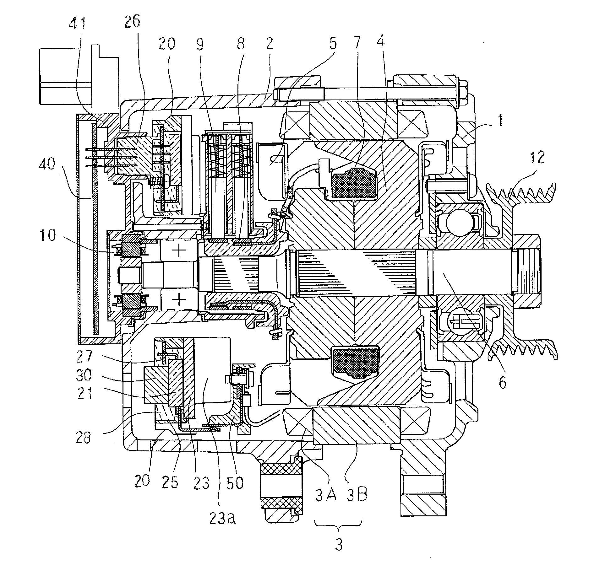
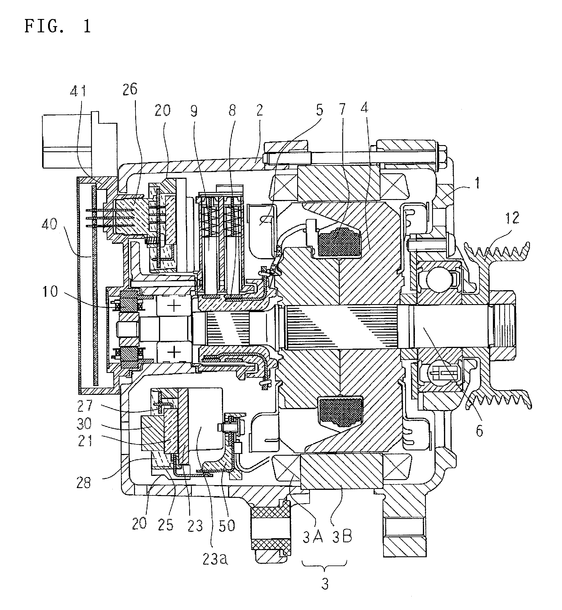
[0018]In FIGS. 1 through 7, a controller-integrated electric rotating machine according to Embodiment 1 is provided with a stator 3 supported by a bracket configured with a front bracket 1 and a rear bracket 2 that are integrally combined with each other. The stator 3 is configured with a stator iron core 3B and a stator winding 3A wound around the stator iron core 3B. A rotor 4 is provided in such a way as to face the inner circumference of the stator 3. The rotor 4 has a magnetic-field winding 7 and rotates in such a way as to be fixed on a shaft 6 supported by a bearing provided in the front bracket 1 and a bearing provided in the rear bracket 2. On the rotor 4, there is mounted a cooling fan 5 for cooling the inside of the electric rotating machine with air.

[0019]This controller-integrated electric rotating machine has an inverter power circuit 20 and a bus bar 30 that is electrically and mechanically joined with the inverter power circuit 20 and formed of a metal material. The ...

embodiment 2

[0036]FIG. 8 illustrates a bus bar of an electric rotating machine according to Embodiment 2 of the present invention. In Embodiment 2, a conductive communication portion 30b between the battery terminal 11 of the bus bar 30 and the bus bar 30 is configured in such a way that the cross-sectional area thereof is smaller than the cross-sectional area of any other portion of the bus bar 30, so that the conductive communication portion 30b has a function as a fuse.

[0037]In the case where a switching element of the power module 21 fails to be short-circuited, the portion between the battery terminal 11, which has the battery potential, and the bracket 2, which has the ground potential, is short-circuited, whereby a large current flows therein, and it is worried that the electric rotating machine may catch fire; however, by making the bus bar 30 also have a function as a fuse, the bus bar 30 is disconnected from the power source at the communication portion 30b of the bus bar 30 in the ca...


PUM


Abstract

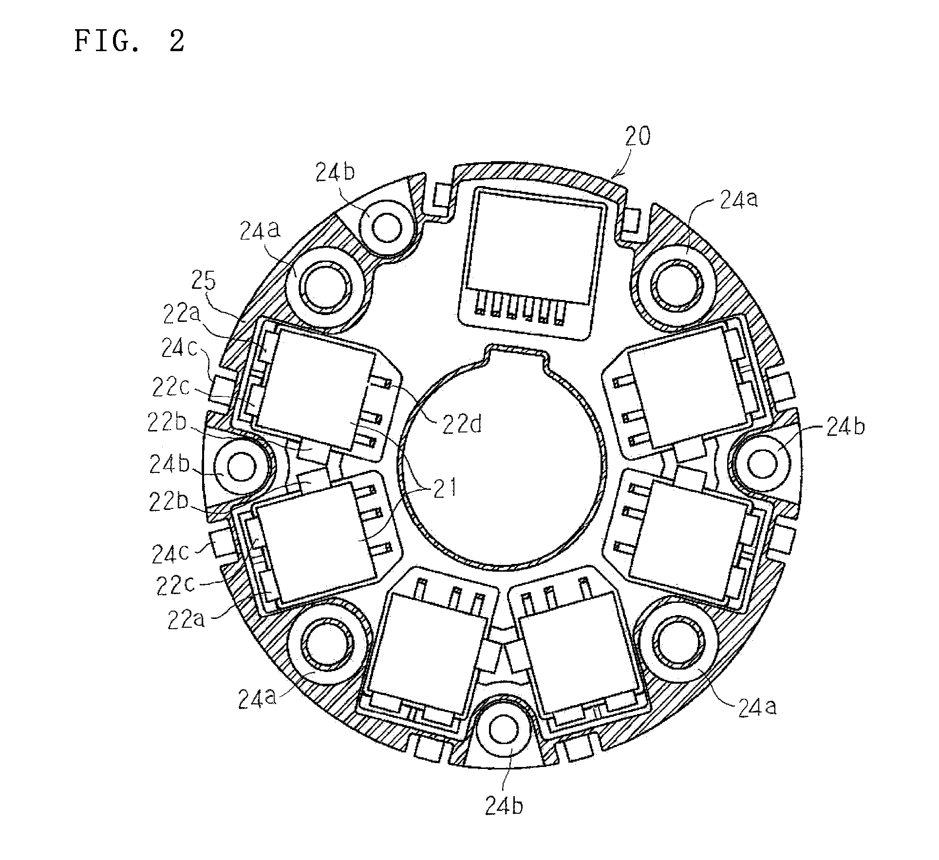
There is obtained a controller-integrated electric rotating machine that is superior in terms of a cooling effect.In a controller-integrated electric rotating machine provided with a stator 3 configured with an iron core 3B and a stator winding 3A, a rotor 4 having a cooling fan 5, an inverter power circuit 20 that is a control apparatus for applying a stator current to the stator winding 3A, and a bus bar 30 that supplies the inverter power circuit 20 with electric power from a battery, the inverter power circuit 20 includes a power module 21 that has a function of switching the stator current, a heat sink 23 on which the power module 21 is mounted by the intermediary of an insulating layer, and an insulator case 25 that incorporates the power module 21 and holds respective terminals of the power module 21; and the bus bar 30 is connected with terminals 22a, 22b, 22c, and 22d of the inverter power circuit 20 and has a cooling fin 30a.

Description

BACKGROUND OF THE INVENTION[0001]1. Field of the Invention[0002]The present invention relates to a controller-integrated electric rotating machine mounted, for example, on a vehicle, and particularly to the cooling structure of an inverter power circuit utilized as a control apparatus for a controller-integrated electric rotating machine.[0003]2. Description of the Related Art[0004]In “an electric-power mutually connecting component for an electric rotating machine” disclosed in National Publication of International Patent Application No. 2008-543261, there is described the configuration of a vehicle power-generation motor for supplying a vehicle with electric power and for driving the engine of the vehicle. In the foregoing Patent Document, there is described the configuration of an electric-power mutually connecting component for inputting electric power to and outputting electric power from an inverter power circuit mounted on an electric rotating machine.[0005]In such a vehicle ...

Claims


Application Information

Patent Timeline
Patent Type & Authority Patents(United States)
IPC IPC(8): H02K1/32
CPCH02K5/18H02K5/225H02K11/048H02K11/05
Inventor ISODA, HITOSHIFUJITA, MASAHIKOTAKECHI, ATSUSHI
Owner MITSUBISHI ELECTRIC CORP
Learn More