
Image processing apparatus and image processing method

a technology of image processing and image signal, applied in the direction of exposure control, color signal processing circuit, instruments, etc., can solve the problems of inability to perform appropriate detection, inability to adequately express the gradation range of an image of a real object, and difficulty in setting an appropriate detection area, etc., to achieve high-quality gradation correction

Inactive Publication Date: 2012-05-29
CANON KK
View PDF5 Cites 0 Cited by
  • Summary
  • Abstract
  • Description
  • Claims
  • Application Information

AI Technical Summary

Benefits of technology

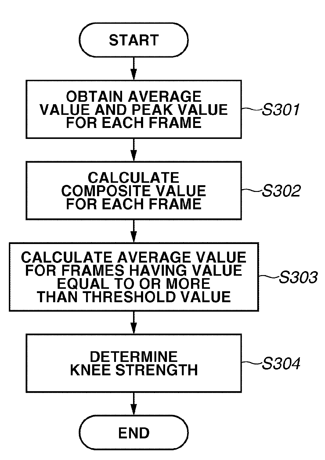
The present invention is about an image processing apparatus and method that can accurately adjust gradation levels even in small areas that may be overexposed in an image. The apparatus includes a luminance value calculation unit, a first calculation unit, a second calculation unit, and a setting unit. The luminance value calculation unit calculates the average and peak luminance values from the image frames. The first calculation unit combines the average and peak luminance values. The second calculation unit calculates the average of composite values that exceed a predetermined threshold. The setting unit then adjusts the knee strength based on the average of the composite values. This invention allows for highly accurate gradation correction in images.

Problems solved by technology

In such an image sensor, a range of gradation expression from black to white levels is narrow, and hence the obtained image signal cannot adequately express a gradation range of an image of a real object.
Hence, when a high luminance level causes overexposure in a certain area of the screen, appropriate detection cannot be performed.
Hence, setting of an appropriate detection area is difficult.

Method used


Image

  • Image processing apparatus and image processing method
  • Image processing apparatus and image processing method
  • Image processing apparatus and image processing method

Examples


Embodiment Construction

[0035]Various exemplary embodiments, features, and aspects of the invention will be described in detail below with reference to the drawings.

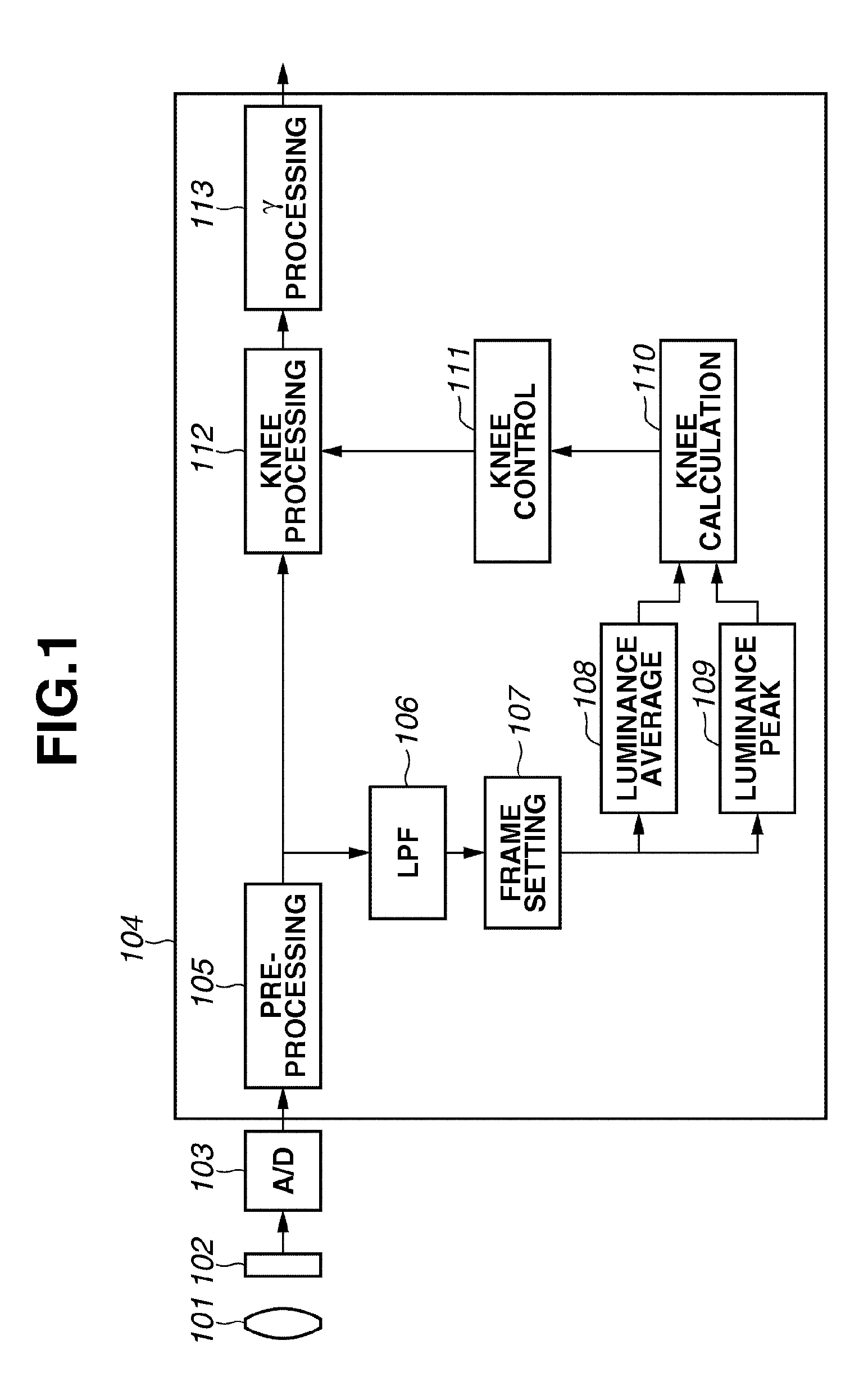
[0036]FIG. 1 is a block diagram schematically illustrating a configuration of an image processing apparatus (a digital video camera or a digital still camera) according to a first exemplary embodiment of the present invention.

[0037]In FIG. 1, the image processing apparatus includes a photographic lens 101, an image sensor 102 such as a CCD or a CMOS, and a camera signal processing unit 104. The image sensor 102 converts an image captured by the photographic lens 101 into an image signal, and an A / D conversion unit 103 further converts the image signal into a digital signal. The camera signal processing unit 104 performs signal processing on the converted image signal and outputs the signal as an image signal recordable in a recording medium (not illustrated).

[0038]The camera signal-processing unit 104 includes a pre-processing circuit 105, a kn...


PUM


Abstract

An image processing apparatus includes a luminance value calculation unit configured to calculate a luminance average value and a luminance peak value from an image obtained by image-capturing for each of frames formed by dividing one screen, a first calculation unit configured to combine the luminance average value and the luminance peak value obtained for each of the frames, a second calculation unit configured to calculate an average value of composite values equal to or more than a predetermined threshold value among composite values obtained by the first calculation unit, and a setting unit configured to set knee strength based on the average value of the composite values obtained by the second calculation unit.

Description

BACKGROUND OF THE INVENTION[0001]1. Field of the Invention[0002]The present invention relates to an image processing apparatus and an image processing method for processing an image captured by a video camera or a digital camera, and more particularly to gradation correction of an image obtained by image-capturing.[0003]2. Description of the Related Art[0004]A conventional imaging apparatus such as a video camera or a digital camera obtains an image signal by using an image sensor such as a charge-coupled device (CCD) or a complementary metal-oxide semiconductor (CMOS). In such an image sensor, a range of gradation expression from black to white levels is narrow, and hence the obtained image signal cannot adequately express a gradation range of an image of a real object.[0005]In a system that digitizes the image signal to record the signal, the gradation range is further restricted to an expression range of a digital signal. In order to solve this problem, knee processing is commonl...

Claims


Application Information

Patent Timeline
Patent Type & Authority Patents(United States)
IPC IPC(8): H04N5/235H04N5/228H04N9/68H04N23/40H04N23/76
CPCH04N5/202H04N5/57
Inventor MAKINO, JUN
Owner CANON KK
Learn More