Image forming apparatus capable of performing accurate gradation correction

a technology of gradation correction and forming apparatus, which is applied in the direction of digitally marking record carriers, electrographic processes, instruments, etc., can solve the problems of inability to accurately measure the high density range, difficulty in detecting the difference in toner amount, and high cost for users, etc., to achieve accurate gradation correction

Inactive Publication Date: 2013-10-08
CANON KK
View PDF4 Cites 0 Cited by
  • Summary
  • Abstract
  • Description
  • Claims
  • Application Information

AI Technical Summary

Benefits of technology

[0010]The present invention provides an image forming apparatus that is capable of performing accurate gradation correction in a range of density which cannot be measured by a toner density detection unit.
[0012]According to the present invention, it is possible to perform accurate gradation correction in a range of density where measurement by the toner density detection unit is impossible.

Problems solved by technology

H07-261479, although gradation correction is performed using a pattern for gradation correction, which is formed on a recording material, this requires a user to place the recording material on which the pattern is formed on an original platen glass, and cause an image reader unit to read the pattern, which costs the user much time and labor.
However, a detection unit which optically measures an amount of toner has a characteristic that if a surface of an image bearing member, such as a photosensitive member, an intermediate transfer member, or the like, is covered with a predetermined amount of toner, even when a larger amount of toner than the predetermined amount is adhered to the surface, a difference in the amount of toner is difficult to be detected.
This causes a problem that in the gradation correction using the optical detection unit, the measurement in the high density range is low in accuracy or is impossible.

Method used


Image

  • Image forming apparatus capable of performing accurate gradation correction
  • Image forming apparatus capable of performing accurate gradation correction
  • Image forming apparatus capable of performing accurate gradation correction

Examples


first embodiment

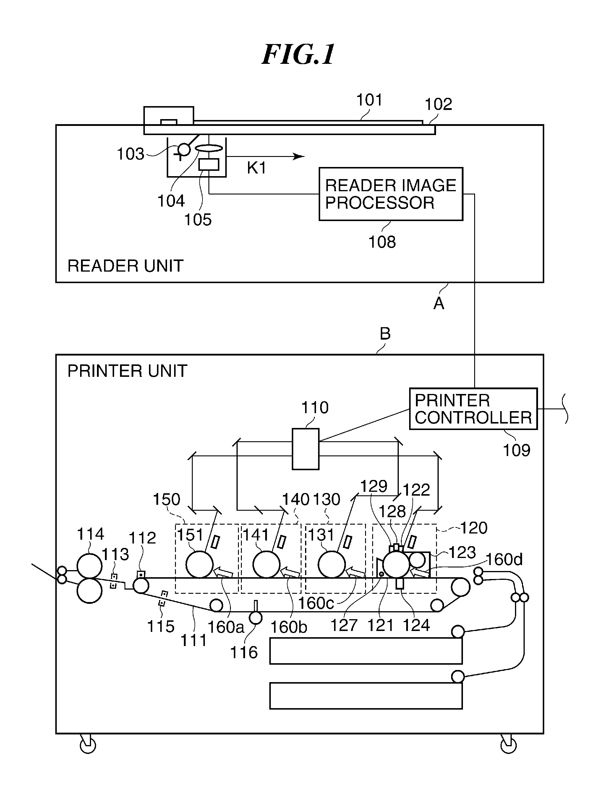
[0031]FIG. 1 is a diagram showing an image forming apparatus according to the present invention.

[0032]In FIG. 1, the image forming apparatus according to the first embodiment of the present invention is implemented e.g. by an electrophotographic color copying machine including a plurality of photosensitive drums (photosensitive members), and comprises a reader unit A and a printer unit B.

[0033]First, the reader unit A will be described.

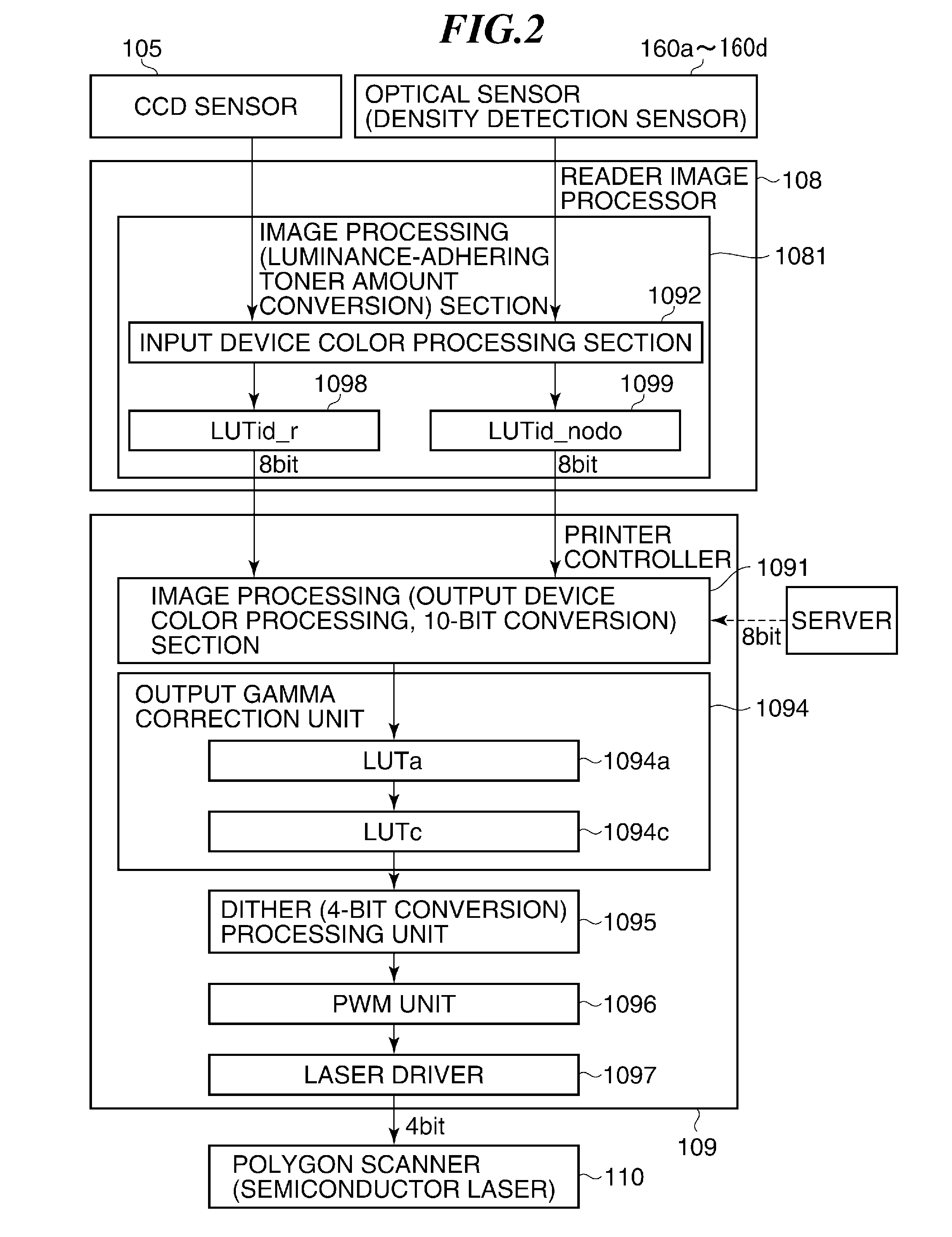
[0034]An original 101 placed on an original platen glass 102 is irradiated with light from a light source 103, and reflected light from the original passes through an optical system 104 to form an image on a CCD sensor 105. The reading unit constituted by the light source 103, the optical system 104, and the CCD senor 105 performs scanning in a direction indicated by an arrow k1 in FIG. 1 to whereby the original is converted to line-by-line electric signal data rows.

[0035]Image signals (image data) obtained by the CCD sensor 105 are subjected to image...

second embodiment

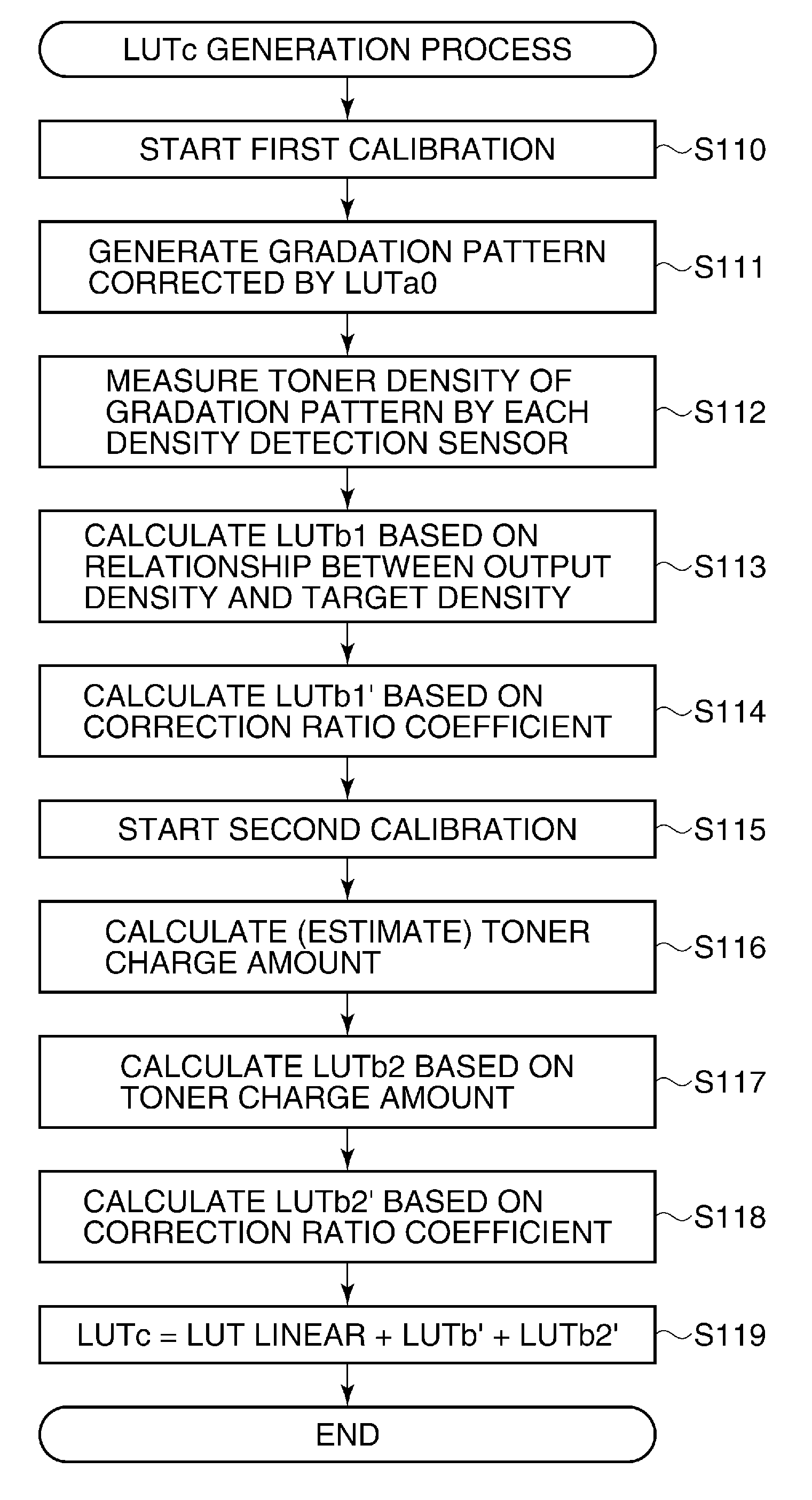
[0079]Next, a description will be given of an image forming apparatus according to the present invention. The present embodiment differs from the first embodiment in a method of correcting gradation such that no boundary of correction is formed in an intermediate portion of the gradation without excessive correction, and the method will be described with reference to FIGS. 9A to 9C. Note that components and operations of the second embodiment, not specified in the following description, are the same as those of the above-described embodiment.

[0080]As shown in FIG. 9A, the correction ratio coefficient for the first calibration and that for the second calibration intersect with respect to the input signal, and they are configured such that each of them is not smaller than 0 and not larger than 1, and the sum of them is not larger than 1. As a result, compared with 10h in FIG. 8C in the first embodiment, a LUTc calculated as shown in FIG. 9B is corrected in a manner not depending on th...

fourth embodiment

[0102]Next, a description will be given of an image forming apparatus according to the present invention. The present embodiment differs from the above-described first to third embodiments in a method of optimizing the correction ratio coefficient for each halftone screen, and hence the method will be described. Note that components and operations of the fourth embodiment, not specified in the following description, are the same as those of the above-described embodiment.

[0103]The image forming apparatus according to the fourth embodiment includes a high resolution screen having approximately 260 lines per inch, which is applied to character part and the like, and a low resolution screen having approximately 150 lines per inch, which is applied to picture part and the like.

[0104]In the low resolution screen, a latent image is formed in an uneven state. Although it is possible to calculate an average charge amount of toner in the second calibration, it is impossible to estimate distr...


PUM


Abstract

An image forming apparatus capable of performing accurate gradation correction in a range of density where measurement by a toner density detection unit is- impossible. A printer unit forms a gradation pattern on an image bearing member. A density detection sensor detects density of the gradation pattern. A first correction value for correcting gradation of the image data is calculated based on density of the gradation pattern, detected by the density detection sensor, and a second correction value for correcting gradation of the image data is calculated based on the estimated condition of toner with which a toner image is formed on the image bearing member. An output gamma correction unit corrects density in a low density range of the toner image based on the first correction value, and corrects density in a high density range of the toner image based on the second correction value.

Description

BACKGROUND OF THE INVENTION[0001]1. Field of the Invention[0002]The present invention relates to an image forming apparatus such as a printer, a copying machine, or the like, that performs image formation e.g. by electrophotography.[0003]2. Description of the Related Art[0004]In printers, copying machines, and the like, that perform image formation e.g. by electrophotography, there has been known calibration for adjusting image quality to desired characteristics by reading an image pattern formed on a recording material and performing density correction and gradation correction. For example, in Japanese Patent Laid-Open Publication No. S62-296669 and Japanese Patent Laid-Open Publication No. S63-185279, as a method of calibrating an output image from an image forming apparatus, there has been proposed a technique of reading image information, such as density, chromaticity, etc. of a specific pattern formed on a recording material, and then feeding back the image information to image...

Claims


Application Information

Patent Timeline
Patent Type & Authority Patents(United States)
IPC IPC(8): H04N1/40
CPCG03G15/5033G03G15/5058H04N1/6033
Inventor NAKASE, TAKAHIRO
Owner CANON KK
Why Eureka
Try Eureka