Supercharge Your Innovation With Domain-Expert AI Agents!

Multichannel echo canceller

a multi-channel, canceller technology, applied in the direction of transducer casings/cabinets/supports, transducers, transmission, etc., can solve the problems of deteriorating sound quality, inability to obtain stable cancelling effect, and unwanted echo of speaker outputting voice, so as to achieve stable cancelling echoes without deteriorating sound quality

Active Publication Date: 2012-05-29
PANASONIC CORP
View PDF14 Cites 31 Cited by
  • Summary
  • Abstract
  • Description
  • Claims
  • Application Information

AI Technical Summary

Benefits of technology

Enables invariably stable echo cancellation in multichannel reproduction without degrading sound quality, effectively handling both single and double talk situations by accurately separating and canceling echoes through independent component analysis.

Problems solved by technology

However, such an acoustic system has a problem that it is required to cancel an echo.
As described above, a voice outputted by a speaker, which has been amplified by the loudspeakers for listening to a voice of another speaker who is present in a remote location, results in an echo which is unwanted for the speaker outputting the voice.
As described above, when the multichannel reproduction is performed, the conventional multichannel echo canceller 9 is not capable of estimating correct transfer characteristics due to inconstant solutions, thereby leading to a problem that an echo cancellation effect cannot be obtained in a stable manner.
However, in a case where a difference in signal levels between channels is small, the technique disclosed in Japanese Patent No. 3407392 cannot correctly determine whether a signal level of each channel is high or low and cannot estimate correct transfer characteristics.
Therefore, the technique disclosed in Japanese Patent No. 3407392 cannot perform the echo cancellation in an invariably stable manner.
Because of this, the additional signals, in addition to a voice of a speaker, are amplified, thereby leading to a problem of deteriorating sound quality due to the additional signals.

Method used


Image

  • Multichannel echo canceller
  • Multichannel echo canceller
  • Multichannel echo canceller

Examples


first embodiment

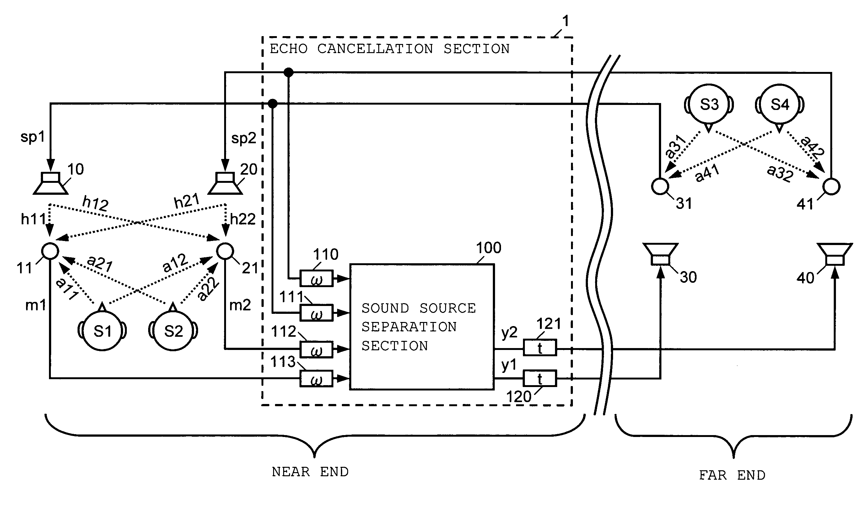
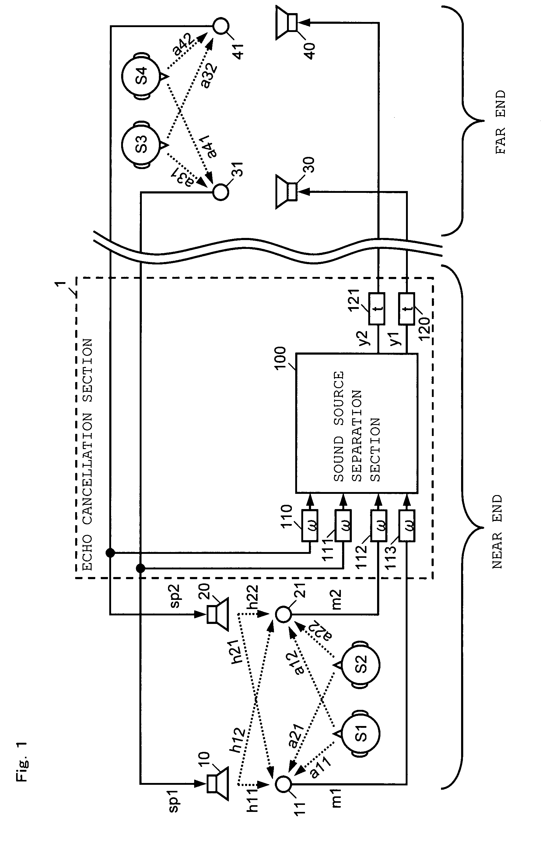
[0045]With reference to FIG. 1, a configuration of a multichannel echo canceller according to a first embodiment of the present invention will be described. FIG. 1 is a diagram illustrating an exemplary configuration of the multichannel echo canceller according to the first embodiment, which is used in an acoustic system. The acoustic system is a system in which acoustic signals are transmitted in an interactive manner between a location on a near end and a location on a far end. In the acoustic system shown in FIG. 1, it is assumed that on the near end, speakers S1 and S2 are present as a plurality of sound sources which are different from each other (near-end sound sources) and on the far end, speakers S3 and S4 are present as a plurality of sound sources which are different from each other (far-end sound sources). On the near end, loudspeakers 10 and 20 for amplifying far-end acoustic signals of voices of the speakers S3 and S4 on the far end and microphones 11 and 21 for detecti...

second embodiment

[0076]With reference to FIG. 3, a configuration of a multichannel echo canceller according to a second embodiment of the present invention will be described. FIG. 3 is a diagram illustrating an exemplary configuration of the multichannel echo canceller according to the second embodiment, which is used in an acoustic system. In an acoustic system shown in FIG. 3, it is assumed that on a near end, a speaker S1 is present as a sound source (near-end sound source) and on a far end, speakers S3 and S4 are present as a plurality of sound sources which are different from each other (far-end sound sources). On the near end, loudspeakers 10 and 20 for amplifying far-end acoustic signals of voices of the speakers S3 and S4 on the far end and microphone 11 and 21 for detecting a near-end acoustic signal of a voice of the speakers S1 on the near end are provided. On the far end, loudspeaker 30 and 40 for amplifying near-end acoustic signals and microphones 31 and 41 for detecting far-end acoust...

third embodiment

[0104]In the above-described first sound source separation section 210 and second sound source separation section 220, all the matrix elements of the separation matrices are updated. In contrast to this, the matrix elements of the separation matrices may be partly constrained (the matrix elements are partly set to be zero). Hereinunder, with reference to FIG. 6, as a third embodiment, a case where the matrix elements of the separation matrices of the first sound source separation section 210 and the second sound source separation section 220 are partly constrained will be described. FIG. 6 is a diagram illustrating a configuration of a first sound source separation section 210a, in which configuration a part of the separation matrix set in the first sound source separation section 210 is constrained.

[0105]In FIG. 6, the first sound source separation section 210a includes a constraint-type separation section 211a and a constraint-type learning section 212a. In the constraint-type sep...


PUM


Abstract

A multichannel echo canceller according to the present invention includes an echo cancellation section which receives loudspeaker input signals sp1, sp2 including a second acoustic signal to be respectively inputted to a plurality of loudspeakers 10, 20 provided in a first location and detection signals m1, m2 detected by a plurality of microphones 11, 21 provided in the first location; separates a first acoustic signal and a second acoustic signal, which are included in the detection signals m1, m2, by performing signal processing based on an independent component analysis; cancels as an echo the second acoustic signal, which is included in the detection signals m1, m2, by outputting only the separated first acoustic signal to a plurality of loudspeakers 30, 40 provided in a second location.

Description

BACKGROUND OF THE INVENTION[0001]1. Field of the Invention[0002]The present invention relates to a multichannel echo canceller and more particularly, to a multichannel echo canceller which is used in a conferencing system, a handsfree telephone, or the like.[0003]2. Description of the Background Art[0004]In recent years, a multichannel acoustic system, such as a conferencing system and a handsfree telephone, in which acoustic signals which are voices of speakers in remote locations are transmitted in an interactive manner has been realized. In a case where this kind of an acoustic system is realized, for example, between a first location and a second location, a plurality of microphones for detecting the voices of speakers and a plurality of loudspeakers with which the voices of speakers in remote locations are listened are provided in the first location and the second location, respectively. The loudspeakers in the first location are connected to the microphones in the second locat...

Claims


Application Information

Patent Timeline
Patent Type & Authority Patents(United States)
IPC IPC(8): H04M9/08A61F11/06H04B15/00
CPCH04M9/082
Inventor NISHIKAWA, TSUYOKIKANAMORI, TAKEOMIZUSHIMA, KOICHIRO
Owner PANASONIC CORP
Features
  • R&D
  • Intellectual Property
  • Life Sciences
  • Materials
  • Tech Scout
  • Unparalleled Data Quality
  • Higher Quality Content
  • 60% Fewer Hallucinations
Learn More