Method for detecting anatomical structures

a technology of anatomical structure and detection method, which is applied in the field of diagnostic image analysis, can solve the problems of patient discomfort, ineffective treatment, and difficulty in detecting the proper position of the et tube using automated image analysis tools

Inactive Publication Date: 2012-05-29
CARESTREAM HEALTH INC
View PDF9 Cites 42 Cited by
  • Summary
  • Abstract
  • Description
  • Claims
  • Application Information

AI Technical Summary

Benefits of technology

[0013]It is an advantage of the present invention that it uses more readily identifiable surrounding structures for locating a more difficult anatomical structure.

Problems solved by technology

Improper tip positioning, on the other hand, can cause patient discomfort, can render a treatment ineffective, or can even be life-threatening.
Detecting proper ET tube position using automated image analysis tools has proved to be challenging.
Flexion and extension of the patient's neck can result in ET tip migration and malpositioning.
When the ET tube is malpositioned within a mainstem bronchus, complete atelectasis of the contralateral lung is likely, accompanied by difficulties with mechanical ventilation.
When the ET tube is malpositioned within the superior trachea, there is a risk of accidental extubation and vocal cord injury.
The use of routine post-intubation chest radiography has been recommended for detection of ET tube malpositioning for which clinical diagnosis is unreliable, since it is often difficult to identify specific pulmonary complications on the basis of clinical examination alone.
However, the carina is often masked by other details of surrounding anatomy, so that it can even be difficult to detect the carina visually in a chest x-ray.
Automated detection can be even more challenging; techniques for computer-assisted carina detection have proved to be error-prone and often less accurate than desirable, making tube and tip malpositioning difficult to detect in some cases.

Method used


Image

  • Method for detecting anatomical structures
  • Method for detecting anatomical structures
  • Method for detecting anatomical structures

Examples


Embodiment Construction

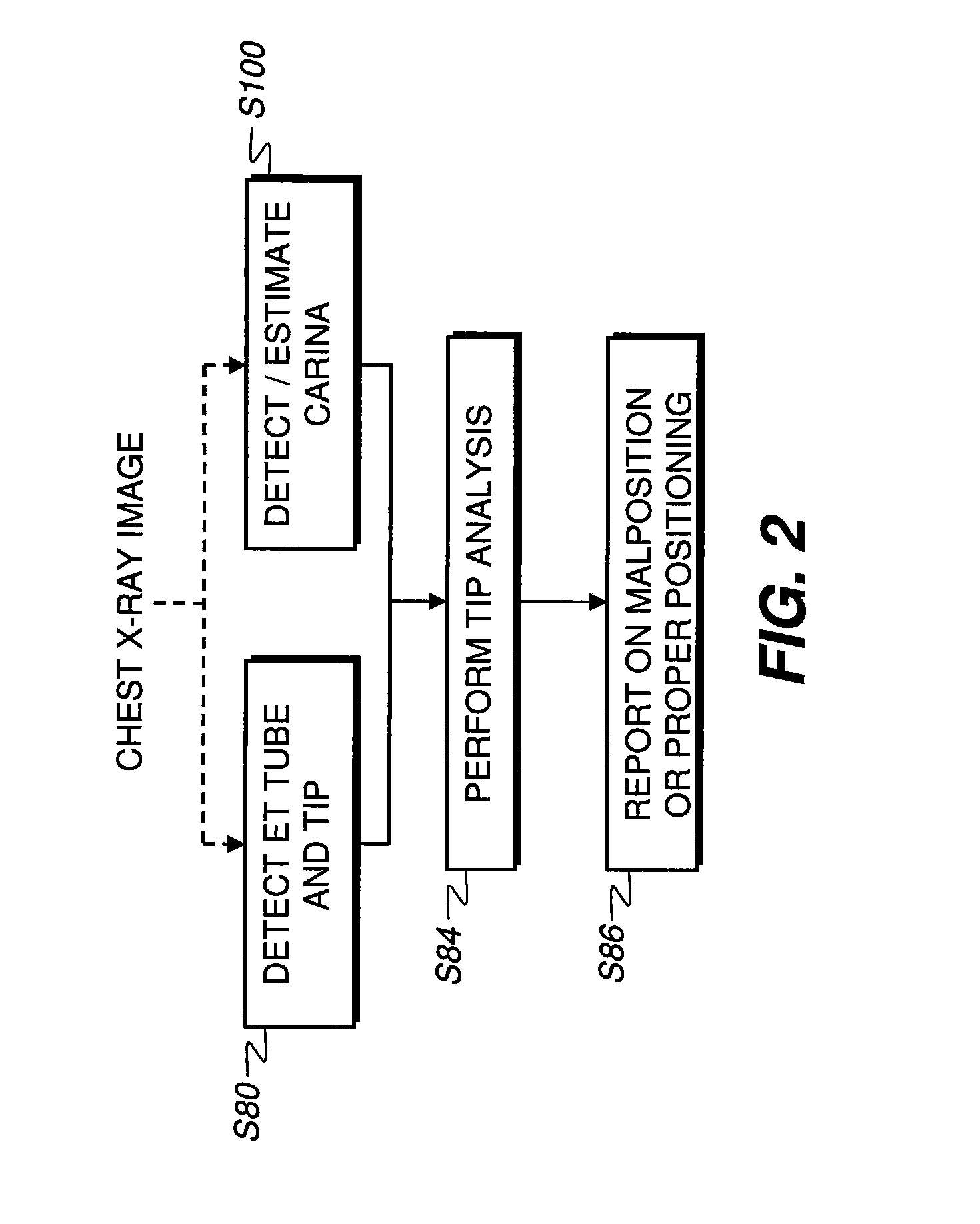
[0030]It is to be understood that elements not specifically shown or described in this description may take various forms well known to those skilled in the art. The sequence of steps of the present invention are executed by a computer or other type of control logic processor that is capable of handling the required amount of image data and that is programmed with appropriate instructions for image analysis and the requisite decision-making. This control logic processor may be provided as part of conventional image processing and display system hardware or may be provided by dedicated hardware or software that accepts and processes input images.

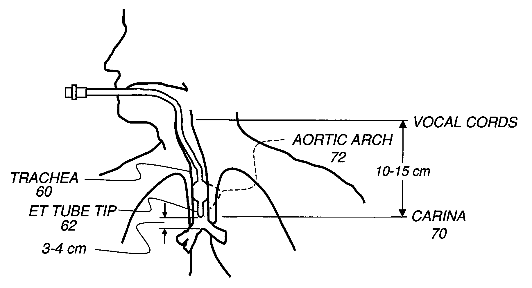
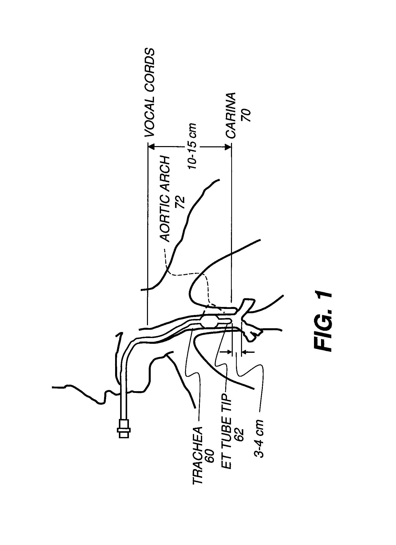
[0031]The description that follows focuses on carina detection for detecting ET tube placement in a chest x-ray as one example of the method of the present invention. It can be appreciated that similar steps would apply for detection of tips for other types of anatomical structures in other types of x-ray or other diagnostic images, with the ...


PUM


Abstract

A method for estimating the location of an anatomical structure in a diagnostic image of a patient obtains the x-ray data in digital format and detects a first benchmark feature within the x-ray image. A second benchmark feature within the x-ray image is detected. An intersection is located between a first line that extends along the length of the first benchmark feature and a second line that extends from a central point related to the curvature of the second benchmark feature and that intersects with the first line at an angle that is within a predetermined range of angles. The location of the anatomical structure is identified relative to the intersection.

Description

CROSS REFERENCE TO RELATED APPLICATIONS[0001]Reference is made to and priority is claimed from the following commonly assigned pending applications:[0002]U.S. patent application Ser. No. 11 / 644,858 and entitled “COMPUTER AIDED TUBE AND TIP DETECTION” by Zhimin Huo and filed 22 Dec. 2006;[0003]U.S. patent application Ser. No. 11 / 942,021 and entitled “IMAGE ANALYSIS OF TUBE TIP POSITIONING” by Huo et al. and filed 19 Nov. 2007; and[0004]U.S. patent application Ser. No. 12 / 172,283 and entitled “COMPUTER-AIDED INTERPRETATION OF ICU PORTABLE CHEST IMAGES: DETECTION OF ENDO-TRACHEAL TUBES” by Zhimin Huo and filed 14 Jul. 2008.FIELD OF THE INVENTION[0005]This invention generally relates to analysis of diagnostic images and more particularly relates to detecting the location of the carina in a chest x-ray.BACKGROUND OF THE INVENTION[0006]Clinical evaluation of patients in an Intensive Care Unit (ICU) often relies on diagnostic images, such as portable chest radiographic images, for example....

Claims


Application Information

Patent Timeline
Patent Type & Authority Patents(United States)
IPC IPC(8): G06K9/00
CPCG06K9/4609G06T7/0044G06K2209/051G06T2207/10116G06T2207/30061G06T7/74G06V10/443G06V2201/031
Inventor HUO, ZHIMINXU, MANTAOZHANG, JING
Owner CARESTREAM HEALTH INC
Why Eureka
Try Eureka