Staple remover

a technology of staple remover and staple, which is applied in the field of hand tools to achieve the effect of effectively removing staples, enhancing ergonomic dexterity and comfor

Inactive Publication Date: 2012-06-05
ROBERTS JOHN D
View PDF6 Cites 1 Cited by
  • Summary
  • Abstract
  • Description
  • Claims
  • Application Information

AI Technical Summary

Benefits of technology

[0006]The staple remover effectively functions to remove staples, especially staples that have been partially removed. The device comprises first and second jaws that are pivotally connected in pliers-like fashion. A flexible hinge structure biases the jaws apart. Each jaw is provided with a toothed or serrated inner surface. The outer surface of each jaw is padded to enhance ergonomic dexterity and comfort. A magnetized, elongate prong (whose function is explained below) extends from the front end of one of the two jaws.
[0007]Accordingly, the invention presents a device for effectively removing staples, which is efficient and durable. The device incorporates features to enhance comfort and effectiveness. The invention provides for improved elements thereof in an arrangement for the purposes described that are inexpensive, dependable and fully effective in accomplishing its intended purposes.

Problems solved by technology

One of the more annoying tasks of office work is that of separating attached paper sheets, especially if the sheets are attached by means of the ubiquitous wire staple.

Method used


Image

  • Staple remover
  • Staple remover
  • Staple remover

Examples


Embodiment Construction

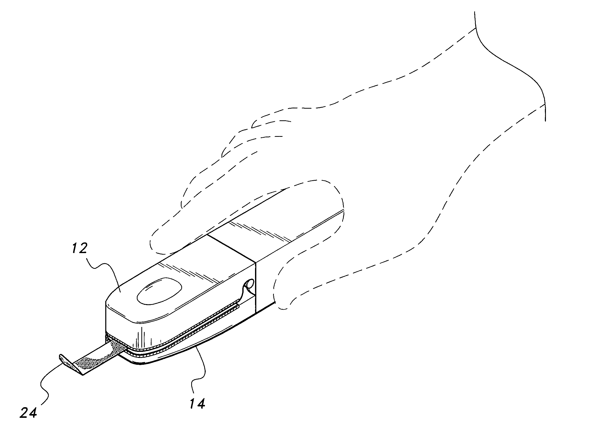
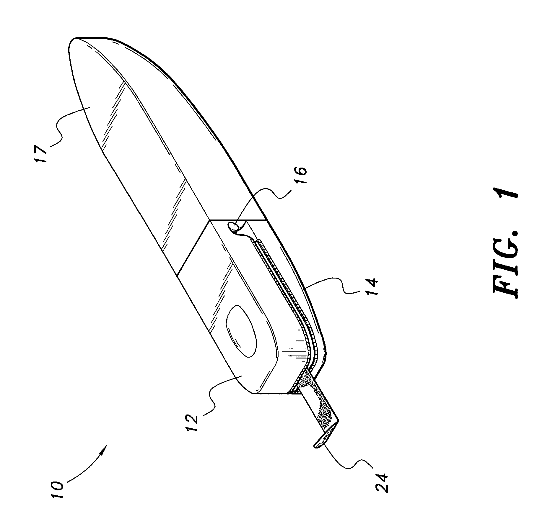
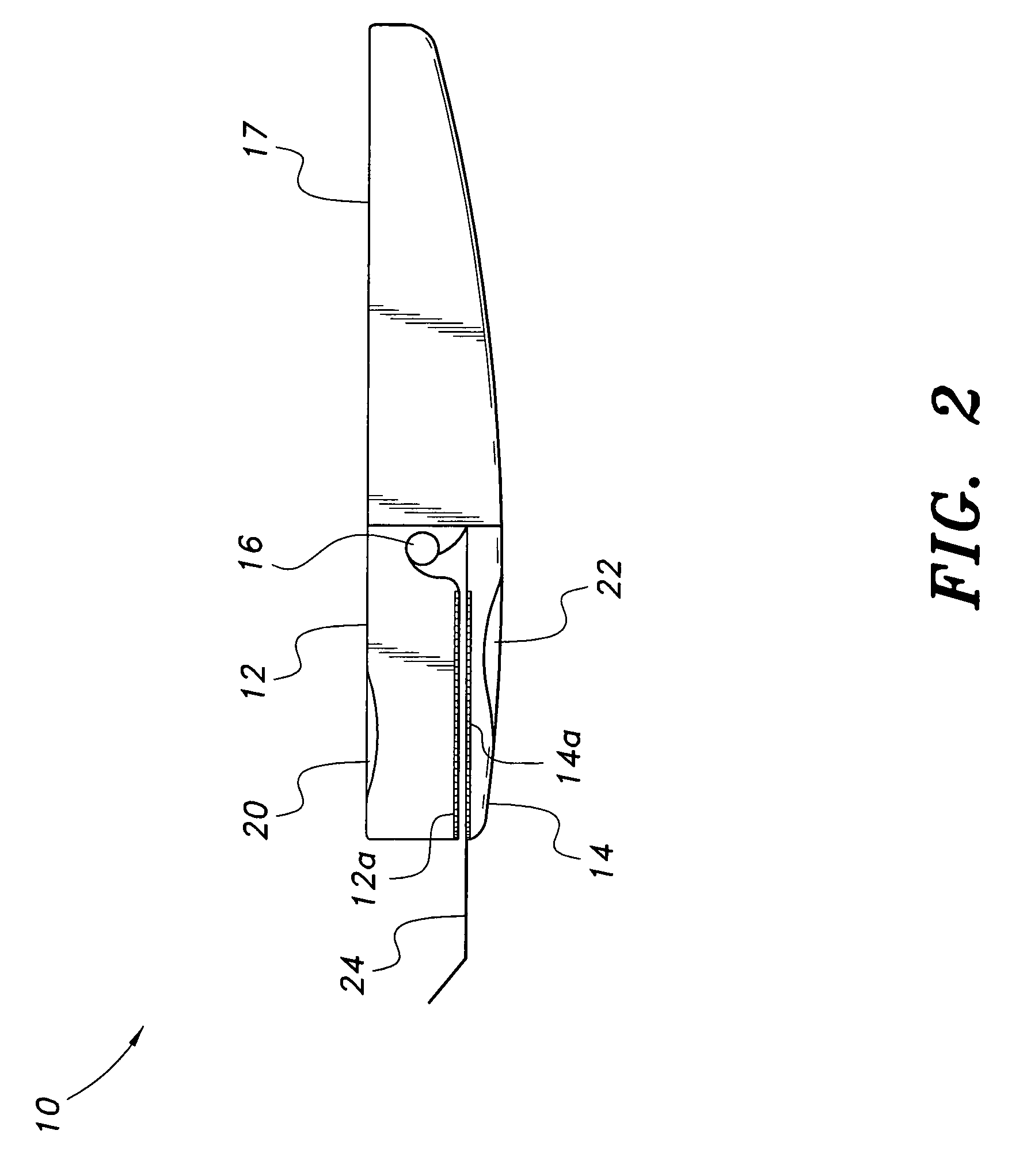
[0018]Referring to FIGS. 1-5, the staple-remover 10 comprises respective first and second jaws 12 and 14 pivotally hinged together at their respective distal ends in a pliers-like arrangement. A resilient, flexible structure 16 defines the hinge. The resilient, flexible hinge 16 can take the form of a coiled spring or any plastic or synthetic material that is sufficiently flexible to bias the jaws apart and permit opening and closing thereof without fatiguing or cracking. A short handle portion 17 extends rearward from the hinge 16. The inner surfaces of each respective jaw 12, 14 are provided with teeth or serrations 12a, 14a for gripping the staples during the removal process. Respective padded indentations 20, 22 are disposed on the outer surface of each jaw 12, 14 to enhance comfort and provide ergonomic facility for the user. A magnetized, elongate prong 24 extends from the front end of jaw 14. Prong 24 is employed to slip under and lift a staple. The staple will be magneticall...


PUM


Abstract

The staple remover is a device that effectively removes staples, especially staples that have already been partially removed. The device includes top and bottom jaws that are pivotally connected in pliers-like fashion. A conventional spring biases the jaws apart. Each jaw is provided with a toothed or serrated-like inner surface. The outer surface of each jaw is padded to enhance ergonomic dexterity and comfort. An elongate prong extends from the front surface of the bottom jaw.

Description

CROSS-REFERENCE TO RELATED APPLICATION[0001]This application claims the benefit of U.S. Provisional Patent Application Ser. No. 61 / 202,296, filed Feb. 17, 2009.BACKGROUND OF THE INVENTION[0002]1. Field of the Invention[0003]The present invention generally relates to hand tools, and more specifically, to a staple remover.[0004]2. Description of the Related Art[0005]One of the more annoying tasks of office work is that of separating attached paper sheets, especially if the sheets are attached by means of the ubiquitous wire staple. Normally, a conventional, jaw-type or pen-type staple puller is employed to remove the wire staples from the sheets. More often than desired, the conventional staple remover only partially removes the wire staple. Efforts, sometimes heroic, must then be made to grasp the staple with one's fingers and completely remove the staple from the paper sheets. A device that could safely and easily remove these partially removed staples would certainly be a welcome a...

Claims


Application Information

Patent Timeline
Patent Type & Authority Patents(United States)
IPC IPC(8): B25C11/00
CPCB25C11/00
Inventor ROBERTS, JOHN D.
Owner ROBERTS JOHN D
Why Eureka
Try Eureka