Device for extracting an elongated structure implanted in biological tissue

a biological tissue and elongated technology, applied in the field of medical devices, can solve the problems of difficult to remove such implanted structures, low blood flow velocity, and encapsulation is especially prone to be encountered

Active Publication Date: 2012-06-05
COOK MEDICAL TECH LLC
View PDF14 Cites 64 Cited by
  • Summary
  • Abstract
  • Description
  • Claims
  • Application Information

AI Technical Summary

Problems solved by technology

However, difficulty is often encountered when attempting removal of such implanted structures, particularly after they have been implanted in biological tissue for a significant period of time.
Encapsulation is especially prone to be encountered in areas where the velocity of the flow of blood is low.
Since the encapsulating fibrotic tissue may be very tough, it is difficult to remove the lead from the area of the heart without causing bleeding or other trauma.
Thus, for example, when small diameter veins through which a pacemaker lead passes become occluded with fibrotic tissue, separation of the lead from the vein can cause severe damage to the vein, or even destruction of the vein in some cases.
Furthermore, separation of the lead from a vein is generally not possible without restricting or containing movement of the lead, that is, fixing the lead in position with respect to the patient, in particular, with respect to the patient's vein.
However, such a practice can incur the risk of an undetected lead thrombosis, which can result in stroke, heart attack, or pulmonary embolism.
Such a practice can also impair heart function, as plural leads can restrict the heart valves through which they pass.
In addition, multiple leads may be incompatible with one another, thereby interfering with their pacemaking or defibrillating function.
Other potentially life-threatening complications can require the removal of the lead as well.
Surgical removal of a heart lead in such circumstances often involves open heart surgery, with its accompanying risks, complications and significant costs.
To the contrary, it is an express purpose of the disclosed device to maintain access to a region of the body lumen about the distal end of the in-place catheter or guidewire during use of the exchange catheter, and receipt of the in-place device in the exchange catheter would interfere with the desired access to that region.
For example, although the devices of Shipko et al. and Booker are generally effective for their intended purposes, these devices are somewhat more complex in structure than may sometimes be preferred, since it is often desirable to employ removal devices having a minimal cross-sectional area.
The device of Amplatz et al. may require a disadvantageously high degree of axial and / or rotational manipulation before the loop can be slipped over the distal end of the device to be removed.
The device of Hyde et al. purportedly avoids this particular problem by having its loop slipped over the proximal end of the in-place device and tightened about it before the exchange catheter is advanced, but not tightened about the in-place device so much that the exchange catheter cannot be readily advanced over the in-place device, or that the in-place device cannot be readily withdrawn.
The device and procedure of Hyde et al. would not be useful for retrieving an elongated structure which has been left in a patient for any extended time, since encapsulation of the structure would prevent any such advancement of the exchange catheter along the structure.
Moreover, kinks or surface defects or irregularities in the in-place device could make it difficult or impossible to achieve a desirably precise degree of tightening of the loop about the in-place device.
Such surface defects or irregularities could result from minor amounts of encapsulating tissue which remain on the in-place device after severing of the in-place device from the bulk of the encapsulating tissue, or from defects or breakage of the in-place device itself.
Finally, although the device of Goode et al. is generally effective for retrieving and removing an implanted lead, the device is not structured to have an aggressive leading end for use in cutting tissue or otherwise extracting an implanted lead from encapsulating tissue.

Method used


Image

  • Device for extracting an elongated structure implanted in biological tissue
  • Device for extracting an elongated structure implanted in biological tissue
  • Device for extracting an elongated structure implanted in biological tissue

Examples


Embodiment Construction

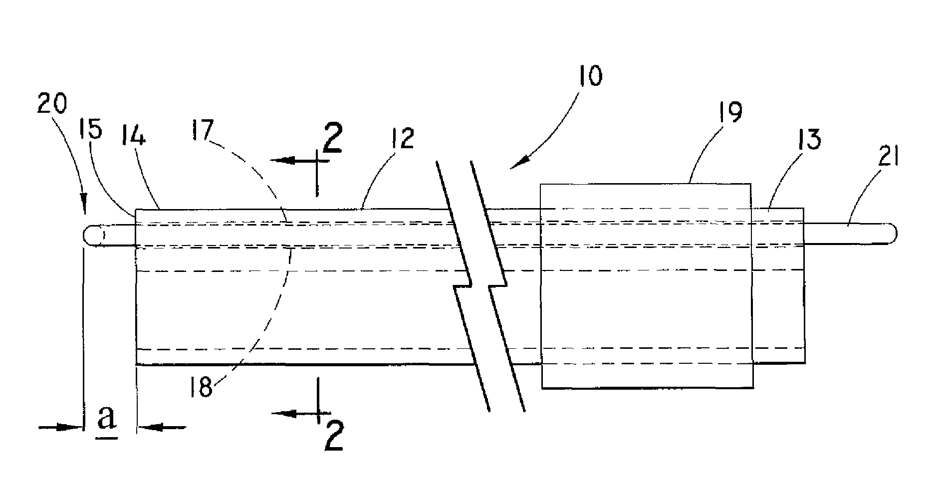
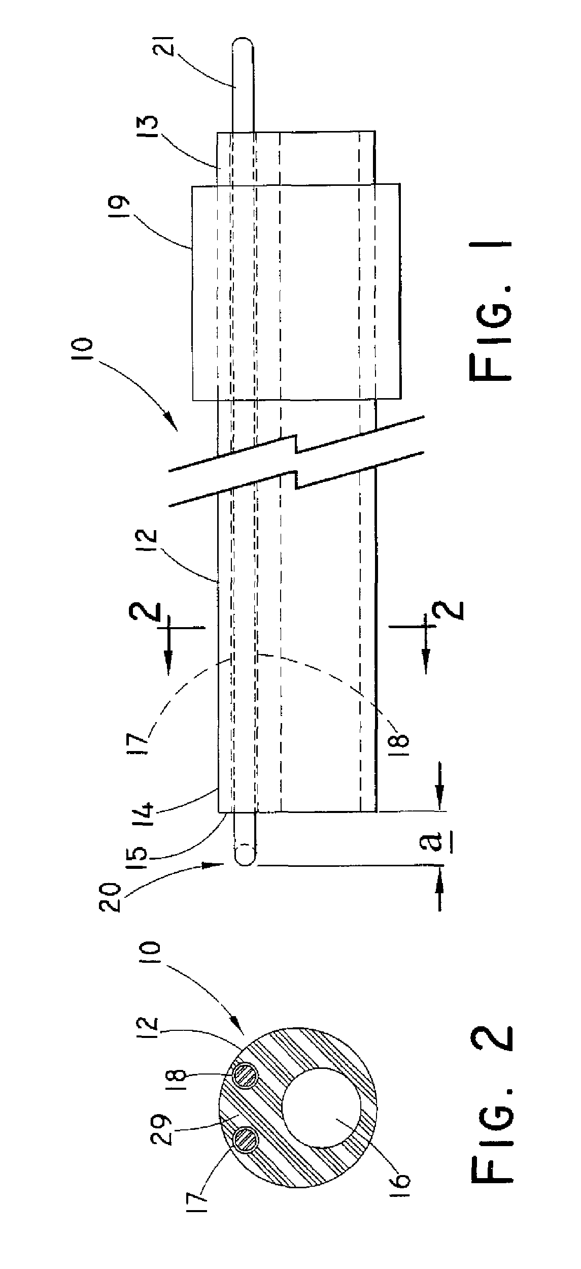
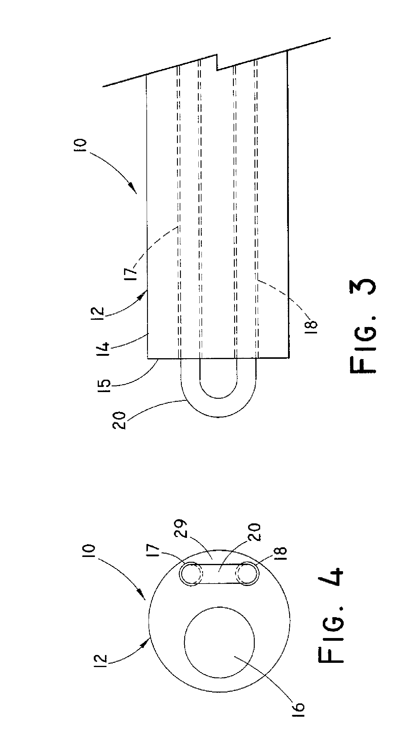
[0033]For purposes of promoting an understanding of the present invention, reference will now be made to the embodiments illustrated in the drawings, and specific language will be used to describe the same. It should nevertheless be understood that no limitation of the scope of the invention is thereby intended, such alterations and further modifications in the illustrated device, and such further applications of the principles of the invention as illustrated therein being contemplated as would normally occur to one skilled in the art to which the invention relates.

[0034]In the following discussion, the terms “proximal” and “distal” will be used to describe the opposing axial ends of the inventive device, as well as the axial ends of various component features. The term “proximal” is used in its conventional sense to refer to the end of the device (or component thereof) that is closest to the operator during use of the device. The term “distal” is used in its conventional sense to r...


PUM


Abstract

A device for extracting an implanted elongated structure from biological tissue comprises a sheath having a plurality of lumens therein opening to the sheath distal end. First and second lumens are disposed along a wall of the sheath, and a third lumen is dimensioned to receive the elongated structure. The sheath wall having the first and second lumens disposed therein is alternately compressible and expandable responsive to a bend along a bending zone of the sheath. A first wire segment is positioned in the first lumen, and a second wire segment is positioned in the second lumen, wherein the respective proximal ends of the segments are affixed proximal to the bending zone. The respective wire segments extend distally in the respective first or second lumen a first distance beyond the distal end of the sheath when the bend compresses the wall surface generally adjacent the first and second lumens, and extend distally a second distance, less than the first distance, when the bend expands the wall surface.

Description

RELATED APPLICATION[0001]The present patent document claims the benefit of the filing date under 35 U.S.C. §119(e) of Provisional U.S. Patent Application Ser. No. 60 / 875,231, filed Dec. 15, 2006, which is hereby incorporated by reference.BACKGROUND OF THE INVENTION[0002]1. Technical Field[0003]The present invention relates generally to a medical device. More particularly, the invention relates to a device for extracting an elongated structure, such as a cardiac electrical lead, that has previously been implanted in biological tissue of a human or veterinary patient.[0004]2. Background Information[0005]A variety of medical treatments and surgical methods entail implanting an elongated structure into the body of a human or veterinary patient. Examples of such elongated structures include catheters, sheaths and cardiac electrical leads (such as pacemaker leads and defibrillator leads), as well as a variety of other devices. Over time, it may become necessary or desirable to remove such...

Claims


Application Information

Patent Timeline
Patent Type & Authority Patents(United States)
IPC IPC(8): A61B18/14A61F7/00
CPCA61B18/1492A61B2018/00601A61B2018/1407
Inventor GOODE, LOUIS B.LUI, CHUN KEE
Owner COOK MEDICAL TECH LLC
Why Eureka
Try Eureka