Performance display system

a display system and display technology, applied in the field of multi-phasic imaging displays, can solve the problems of insufficient stability, inability to achieve any acceptance, and inability to achieve sufficient resolution or stability, and achieve the effect of low cos

Inactive Publication Date: 2012-06-05
SOLOMON DENNIS J
View PDF7 Cites 14 Cited by
  • Summary
  • Abstract
  • Description
  • Claims
  • Application Information

AI Technical Summary

Benefits of technology

[0012]The present invention discloses an improved and versatile performance display systems which includes a method and device for the low cost, real-time, precision control of audio or visual effects such that an affordable uniform appliance distributed, affixed, attached, accompanying or held by each member of an audience or group would seamlessly, and without error, integrate in a global screen or orchestra in real-time.
[0014]Another object of the invention is a reduction in the cost and energy required to operate the performance audience unit system.

Problems solved by technology

A few inventions have been proposed which have generally been too complicated to be reliable, expensive to manufacture, without sufficient resolution, or sufficient stability to gain any acceptance.
While inventive and functional, the Sako design remains awkward and requires considerable energy to maintain an image.
For these reasons, it is unsuitable for entertainment, marketing and game applications.
None of these or the other prior art has successfully addressed the problem of providing low cost, real-time, precision control of audio or visual effects such that an affordable uniform appliance distributed, affixed, attached, accompanying or held by each member of an audience or group would seamlessly, and without error, integrate in a global screen or orchestra in real-time.
None of the prior inventions was capable of independent and concerted three-dimensional visual effects.
None permitted the simultaneous registration of all units.
Further, a number of other problems have remained including the development of switching methodology which permits a static on-off state, display freedom from inertial changes, a frame of reference and global orientation.

Method used


Image

  • Performance display system
  • Performance display system
  • Performance display system

Examples


Embodiment Construction

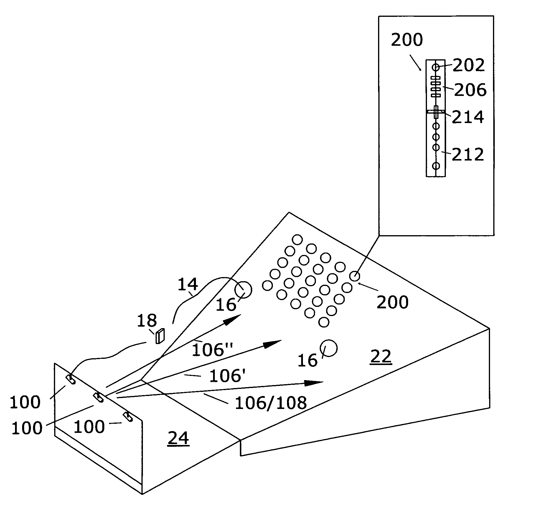
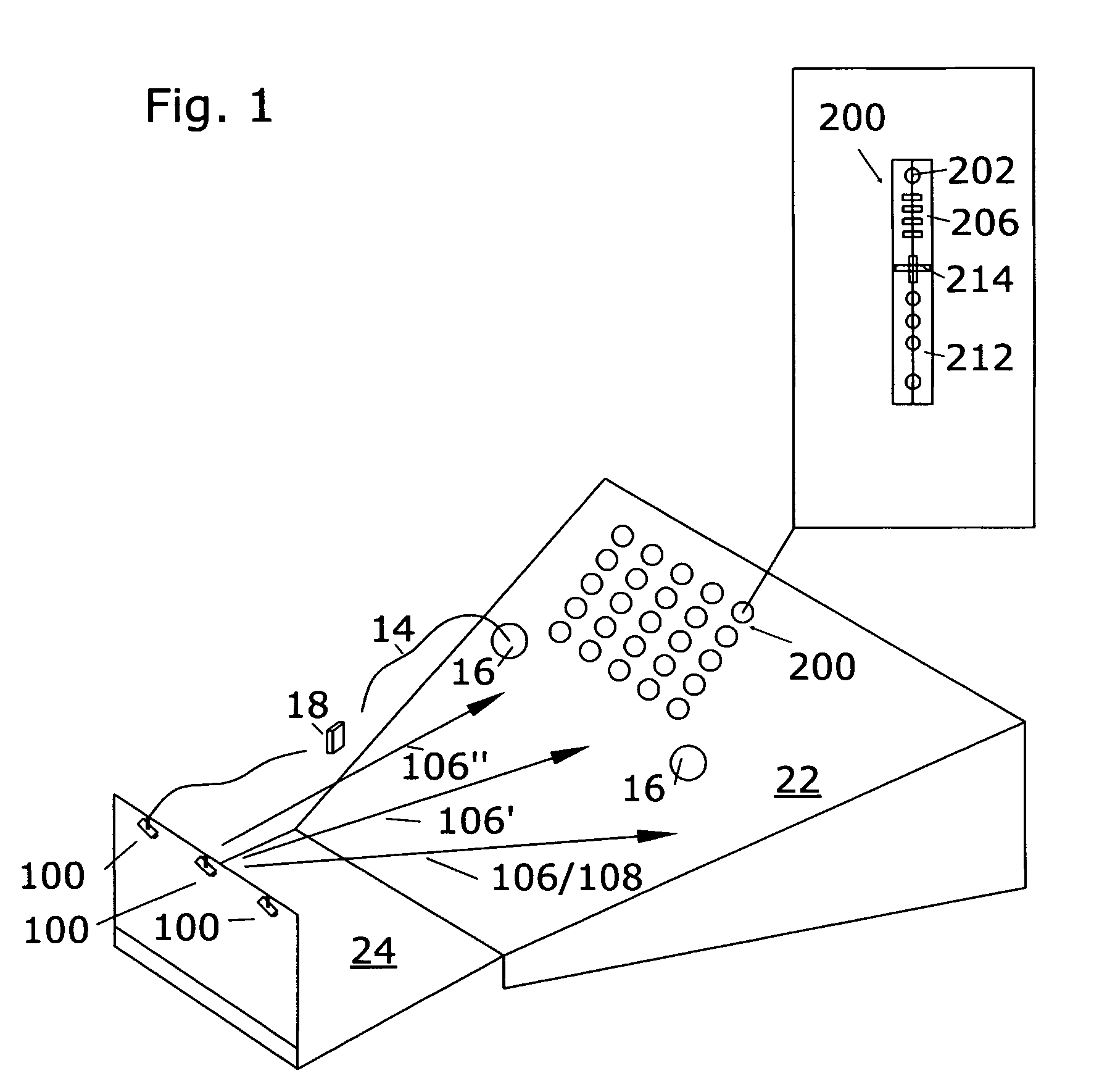
[0048]FIG. 1 presents the generalized elements of the performance display system 10 in a venue 22 resembling a stage 24. The venue 22 may include any space ranging from an automobile to sporting event venue 20 such as at a football stadium.

[0049]Although the term audience unit 200 is used to describe the simple and autostereoscopic-effects unit, it may be understood that the module may take any shape or be incorporated into any independent handheld, worn, or positioned effects device including but not limited to tickets, badges, buttons, globes, cylinders, signs, sashes, headdresses and emblems affixed to any object, moveable or stationary.

[0050]The insert in FIG. 1 presents a front view of the present invention having an illuminated audience unit 200 with some or all of the elements of the audience unit of FIG. 1, having one or more light emitting elements 206, a connecting member 214, handle 212 and an active receiver 202 capable of receiving optical or acoustic signals.

[0051]In o...


PUM


Abstract

An Improved method and device for entertainment and the display of images incorporating the audience in a performance including the integration of independent,-mobile three-dimensional audience display elements. Improved methods for manufacturing an integrated visual display incorporating scanned light sources in the audience display elements.

Description

[0001]This present application claims the benefit and is a continuation-in-part of U.S. patent continuation-in-part application Ser. No. 11 / 149,638 filed in Jun. 9, 2005 now abandoned; Ser. No. 10 / 941,461 filed in Sep. 15, 2004 now abandoned; Ser. No. 10 / 385,349 filed on Mar. 10, 2003 now abandoned; Ser. No. 10 / 307,620 filed on Dec. 2, 2002 now abandoned; Ser. No. 10 / 172,629 filed on Jun. 14, 2002 now abandoned; Ser. No. 09 / 793,811 now abandoned filed on Feb. 24, 2001; and of provisional patent application 60 / 212,315 filed Jun. 16, 2000 and 60 / 558,238 filed Mar. 31, 2004 which are incorporated herein in their entirety by reference.TECHNICAL FIELD[0002]This invention relates generally to performance display devices and more particularly to multi-phasic imaging displays.BACKGROUND ART[0003]The engagement of the audience in a display environment has been the goal of inventors since the origins of art. Significant advances in the displays have been accomplished including cycloramas, int...

Claims


Application Information

Patent Timeline
Patent Type & Authority Patents(United States)
IPC IPC(8): H04N15/00H04N13/393
CPCH04N13/0402H04N13/0493H04N13/302H04N13/393
Inventor SOLOMON, DENNIS J
Owner SOLOMON DENNIS J
Why Eureka
Try Eureka