Movable-body navigation information display method and movable-body navigation information display unit

a technology of movable bodies and navigation information, which is applied in the direction of navigation instruments, mechanical control devices, instruments, etc., can solve the problems of not being able to determine what position and not being able to capture the road, and achieve accurate projection, accurate recognition of relation, and favorable visibility

Inactive Publication Date: 2012-06-05
NAT UNIV CORP KUMAMOTO UNIV
View PDF56 Cites 71 Cited by
  • Summary
  • Abstract
  • Description
  • Claims
  • Application Information

AI Technical Summary

Benefits of technology

[0029]In view of the foregoing, it is an object of the invention to provide a navigation information display method and a movable-body navigation information display unit. In the navigation information display method and the movable-body navigation information display unit, navigation information such as a course guide, a vehicle position, and map information is accurately projected and displayed in an appropriate position in a real picture or in a real landscape of the road ahead of the movable body. Thereby, a driver can intuitively and accurately recognize a relation between the navigation information and the real picture or the real landscape. In addition, visibility of a caution-needed picture such as a pedestrian in the real picture and a real picture of a road construction site is not blocked by the image of the navigation information.
[0053]As described above, according to the movable-body navigation information display method or the movable-body navigation information display unit of the invention, the road shape model of the road assumed to be captured from the current position is created based on the current position of the movable body such as a motor vehicle and the road map data including the current position, the road shape data as the image data of the road included in the landscape ahead of the vehicle or in the traveling direction is extracted from the real picture, the data of the road shape model is matched with the road shape data to estimate the posture data of the in-vehicle camera or the movable body to the road in the landscape as the object, the appropriate display position in the captured real picture of the navigation information read according to the current position of the movable body is determined based on the posture data, and the image in which the read navigation information is composited in the determined appropriate position in the captured real image is displayed. Therefore, for example, the navigation information such as a course guide, a vehicle position, and map information can be accurately projected and displayed in an appropriate position in the real picture or in the real landscape of the road ahead of the movable body. Thereby, the driver can intuitively and accurately recognize a relation between the navigation information and the real picture or the real landscape. In addition, visibility of a caution-needed picture such as a pedestrian in the real picture and a real picture of a road construction site is not inhibited by the image of the navigation information. Consequently, the visibility can be favorable over the entire display image.

Problems solved by technology

However, in the technique disclosed in the Patent document 1, there are problems as follows.
Therefore, in the case of displaying the navigation information on a curved road or in the case of a road provided with multi-lanes such as two lanes on each side, there are the problems as follows.
That is, it is not possible to determine what position in the landscape the navigation information display accurately indicates.
However, in the case of a general passenger car, or even in the case of a vehicle such as a bus and a track with the driver seat located in a high position, there is no possibility that the road landscape actually seen through the windshield from the driver seat of the vehicle becomes a bird's-eye view down from a high position as shown in FIG. 13.
In other words, except for a driver seat located in an extremely high position being 10 m or more high from the ground such as a cockpit of a jumbo jet that is unlikely to exist as a driver seat of a motor vehicle, it is not possible actually to capture the road picture in the landscape in which buildings and houses are crammed side by side as the bird's-eye view with which even turning points and back roads of the buildings can be seen as shown in FIG. 13.

Method used


Image

  • Movable-body navigation information display method and movable-body navigation information display unit
  • Movable-body navigation information display method and movable-body navigation information display unit
  • Movable-body navigation information display method and movable-body navigation information display unit

Examples


Embodiment Construction

[0069]An embodiment of the invention will be hereinafter described in detail with reference to the drawings.

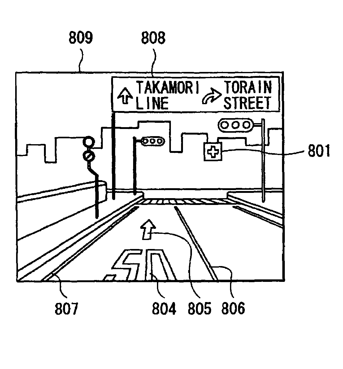
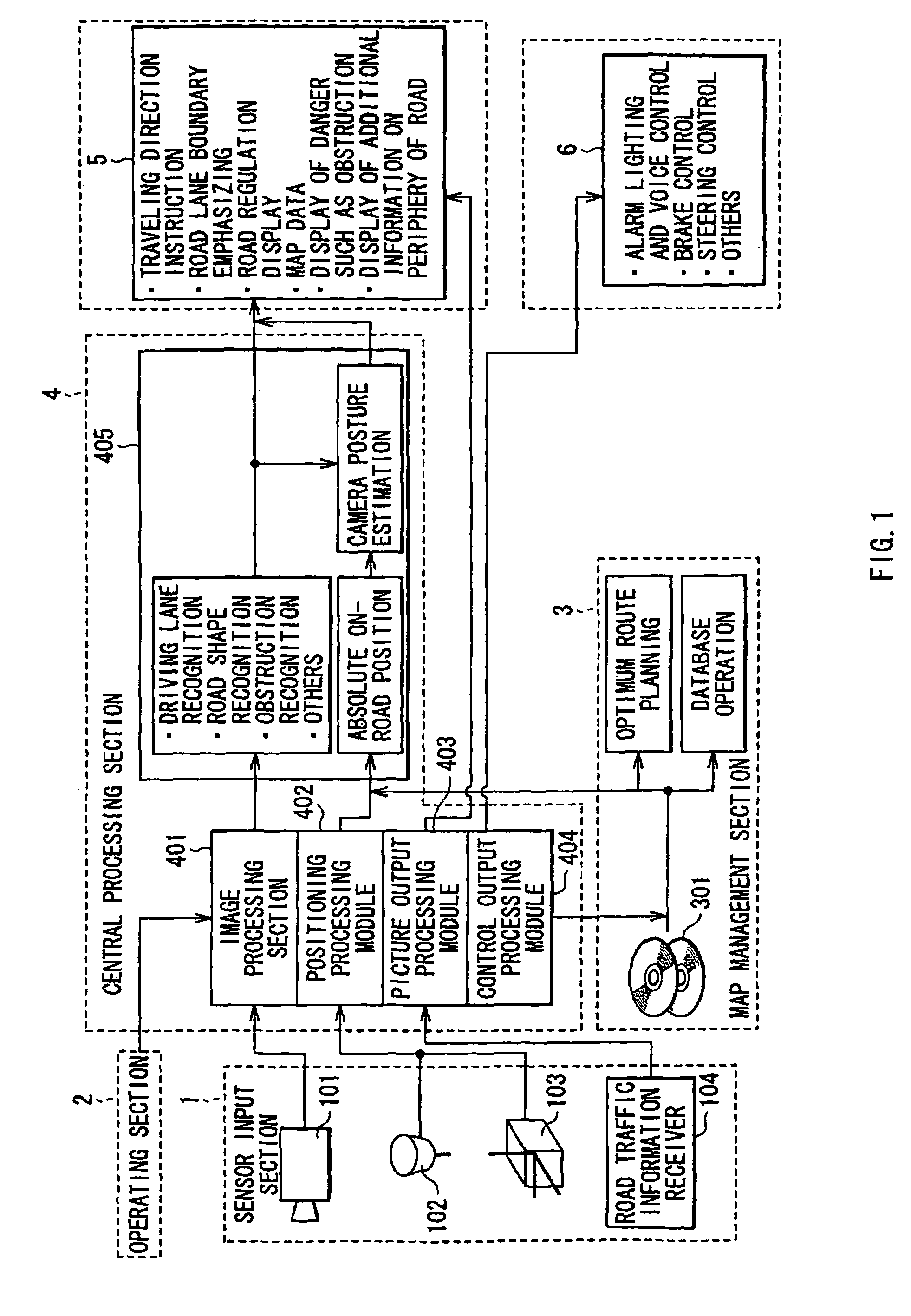
[0070]FIG. 1 shows an outline structure of a movable-body navigation information display unit of the invention. A movable-body navigation information display method according to an embodiment of the invention is embodied by operations or functions of the movable-body navigation information display unit. Therefore, a description will be given of both the movable-body navigation information display unit and the movable-body navigation information display method together.

[0071]The movable-body navigation information display unit includes a sensor input section 1, an operating section 2, a map managing section 3, a central processing section 4, a picture display section 5, and a controlling section 6 as the main sections.

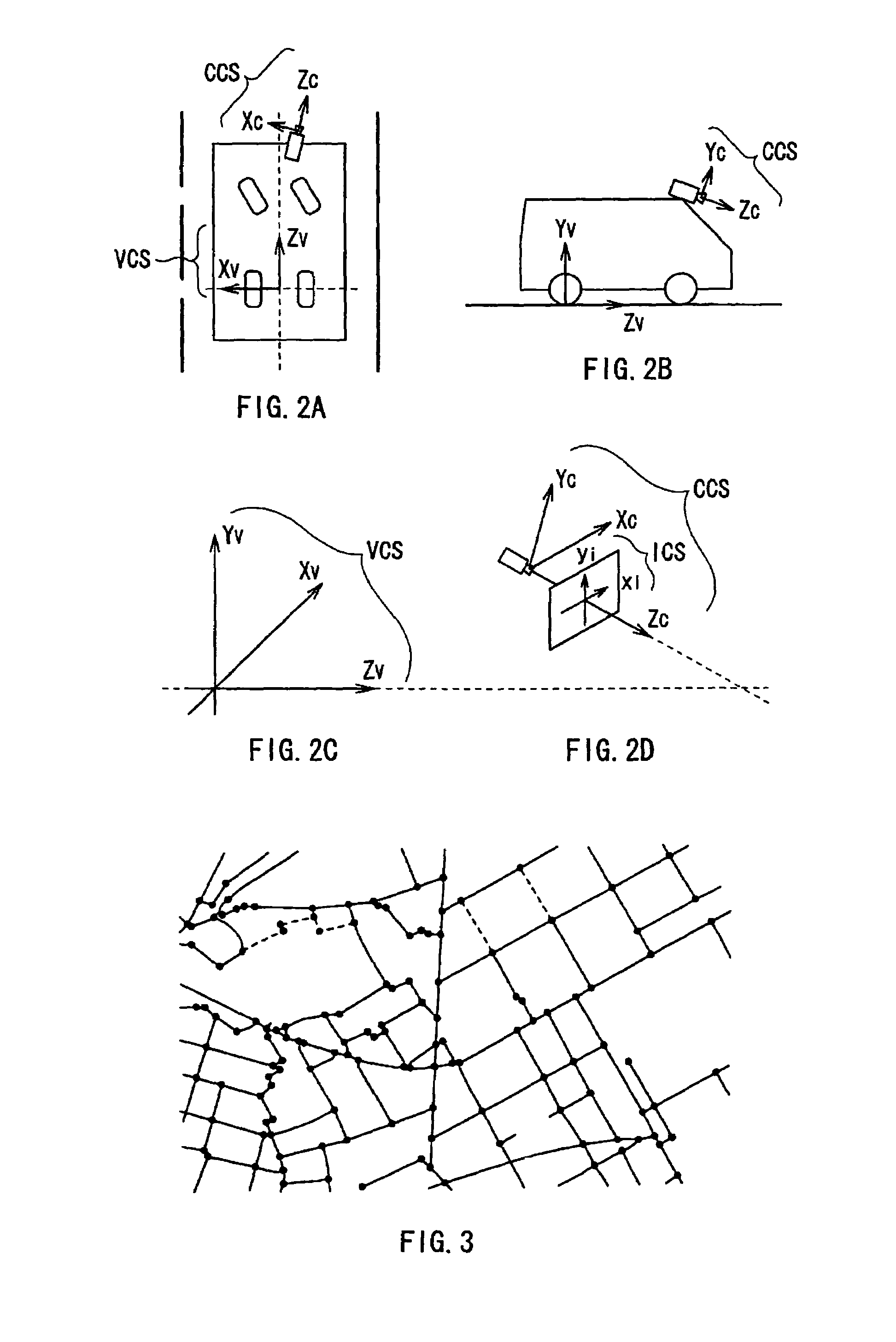
[0072]More specifically, the sensor input section 1 includes a CCD (solid-state image sensing device) camera 101, a GPS sensor 102, an INS sensor 103, and a VICS ...


PUM


Abstract

A movable-body navigation information display unit is provided. In the movable-body navigation information display unit, a driver can intuitively and accurately recognize a relation between navigation information and a real picture or a real landscape. In addition, it is possible to avoid a state that visibility of a caution-needed picture such as a pedestrian in the real picture and a real picture of a road construction site is inhibited by an image of the navigation information. An image data creating section (405) matches road shape data with a road shape model to estimate posture data. In addition, the image data creating section creates picture (image) data for accurately compositing and displaying the image of the navigation information in an appropriate position in a real picture (or in a real landscape) of a road ahead of a movable body, and displays the navigation information as a three-dimensional icon or the like. A picture display section (5) performs display based on the picture data.

Description

TECHNICAL FIELD[0001]The present invention relates to a movable-body navigation information display method and movable-body navigation information display unit for, for example, collecting, processing, and displaying information on a current position of a movable body and information for navigation related thereto, such as a so-called car navigation system and a display method of car navigation information thereby.BACKGROUND ART[0002]movable-body navigation system such as a so-called car navigation system has been developed. In the movable-body navigation system, a current position of a movable body such as a motor vehicle is detected, the detected current position is displayed on a display screen together with a road map of surroundings, various guide information such as a destination and a route is displayed, and voice output is made.[0003]In such an existing car navigation system, the current position of the movable body is checked as follows. That is, an autonomous-navigation co...

Claims


Application Information

Patent Timeline
Patent Type & Authority Patents(United States)
IPC IPC(8): G05G5/00
CPCG01C21/3647G01C21/365G08G1/096861G08G1/0969
Inventor HU, ZHENCHENGUCHIMURA, KEIICHI
Owner NAT UNIV CORP KUMAMOTO UNIV
Why Eureka
Try Eureka