[0006]The methods, devices, and systems of the invention each have several aspects, no single one of which is solely responsible for its desirable attributes. Without limiting the scope of this invention, its more prominent features will now be discussed briefly. After consideration of this discussion and particularly after reading the section entitled “Detailed Description of Preferred Embodiments,” one will understand how the features of the invention provide advantages that include, for example, a technology related to hydroelectric generation that has low environmental
impact, good aesthetics, and requires low maintenance and low cost construction.
[0007]Certain preferred embodiments of the present invention provide a method of using instream
river water flow velocity to increase turbine output. In one embodiment, the method comprises capturing the
kinetic energy in flowing
river water, preferably in water spilling over low-head dams, and using such energy in conjunction with differentials between head water and turbine location to improve turbine output. In certain implementations, the novel technology can be used to establish dispersed small-scale hydroelectric generation units at existing low-head dams. Preferably, the dispersed small-scale hydroelectric generation units can be connected to the existing
power grid, thus providing a new source of sustainable
alternative energy.
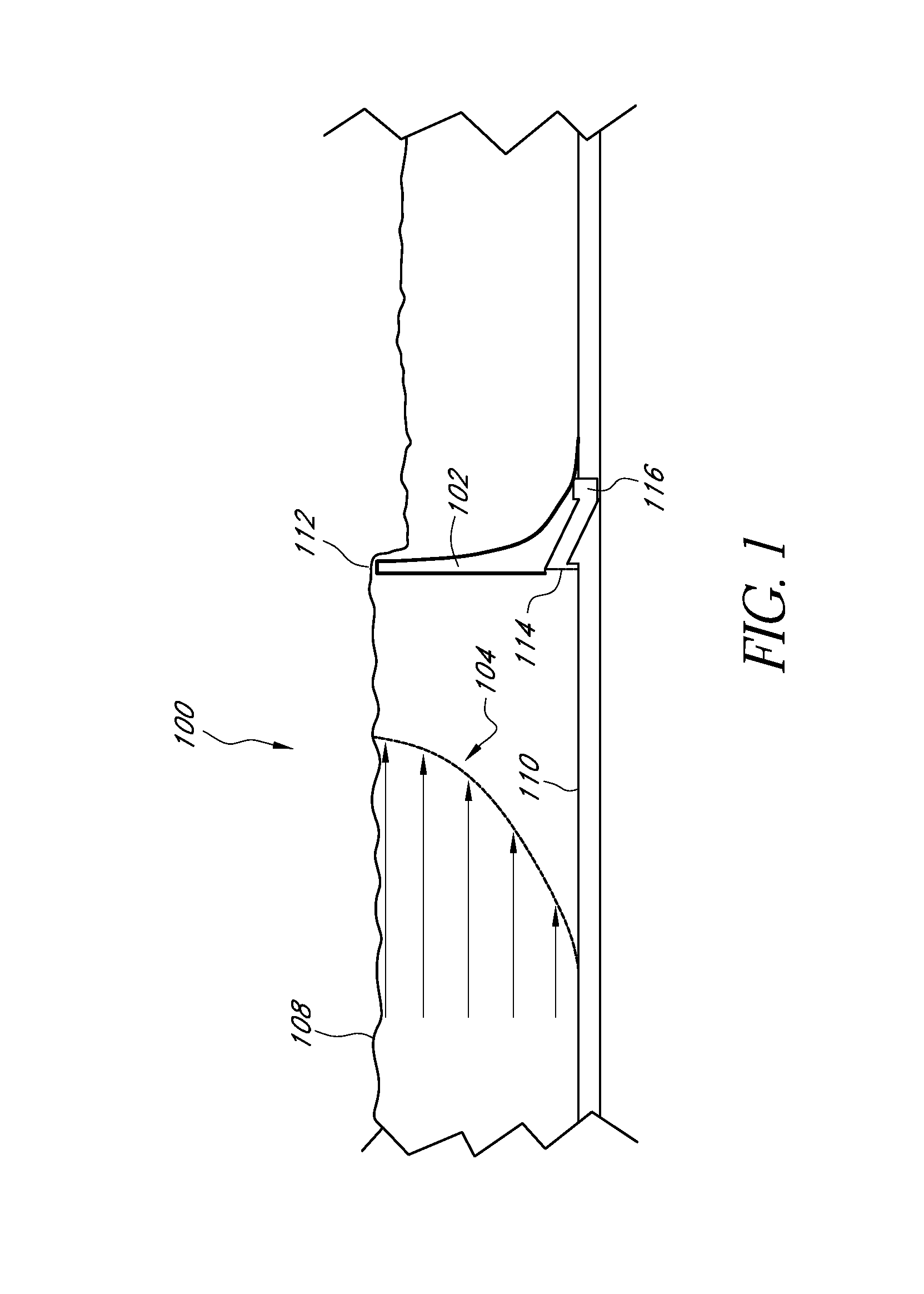
[0009]In another implementation, the method further comprises positioning the turbine generator at an elevation below the intake and using vacuum to
siphon flowing water over the dam to utilize the
kinetic energy added to the
potential energy available from the elevation drop between upper and lower reservoirs to increase the total turbine output. In another implementation, the method comprises providing a draft tube on the downstream side. The draft tube is preferably designed to further improve the unit performance by providing the suction at the
discharge end to reduce instream pressure losses. In one implementation, the method comprises utilizing the energy from the flowing water in conjunction with vacuum technology to establish the velocity heads which are added to the head drops over the existing dam. In some embodiments, the method further includes providing an intake structure that transforms from a square flat configuration to circular configuration that preferably spirals down to the turbine runner.
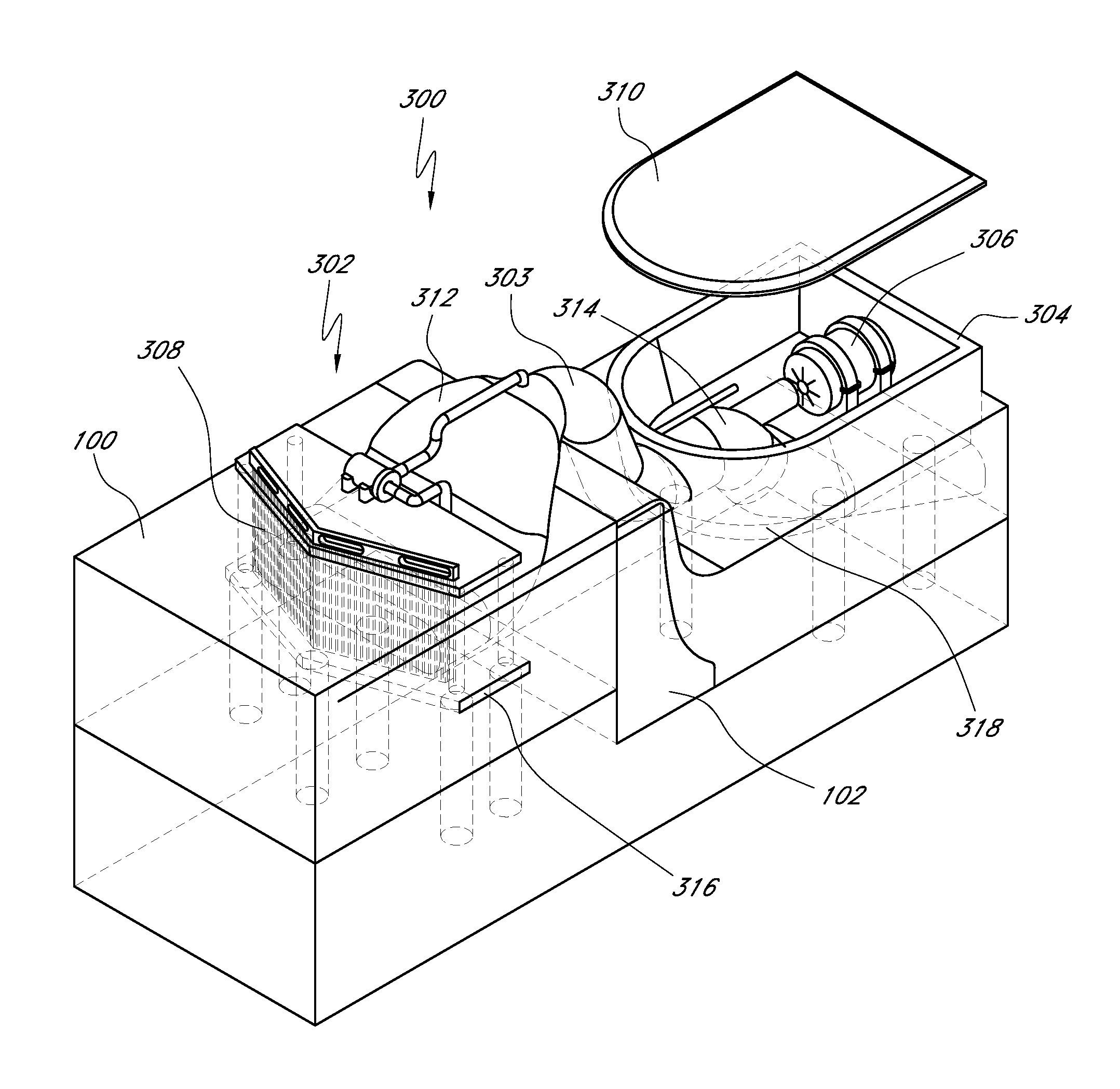
[0011]Another preferred embodiment of the present invention provides a compact, low-profile instream flow turbine generator
system. The
system comprises a turbine and a low-profile intake system adapted to reduce
water velocity loss and facilitate positioning of the intake system over existing low-head dams. In one embodiment, the intake system comprises a
penstock having a substantially square, flat configuration at a proximal end and transitions to a circular configuration at a distal end. In another embodiment,
grating and screens are positioned on the front end of the system to keep out debris and the like. In another embodiment, the system further comprises a vacuum
siphon to assist in drawing water into the system. The
penstock is preferably designed to be positioned over the dam in certain embodiments, which substantially minimizes the
impact on existing dams and increases the
power output with an improved net head. In one implementation, the intake system preferably comprises a low profile
penstock positioned above the dam having a circular tube leading to a turbine runner chamber. The configuration of the intake system is preferably adapted to reduce the loss of fluid velocity as water travels through the system.
[0013]Certain other preferred embodiments of the present invention provide a method of using pump discharge flow velocity from reservoir pumping stations to increase turbine output. In one embodiment, the method comprises harnessing the kinetic energy in pump discharge flow and using such energy in conjunction with differentials between head water and turbine location to increase turbine output. In one implementation, the method comprises positioning the intake of a turbine generator instream a pump discharge flow at pumping stations and positioning the turbine generator at an elevation lower than the intake. Preferably, the kinetic energy in the pump discharge flow in conjunction with the differentials between head water and turbine location increase the total turbine output. In one embodiment, the intake structure comprises a square flat configuration that transforms to a circular configuration and preferably spirals down to the turbine runner.

