Heat exchanger structure

A technology of heat exchangers and joints, which is applied in the direction of household heating, heating methods, household heating, etc., can solve the problems of serious air leakage, space occupation, and low efficiency of electric heating, so as to improve efficiency and unit performance, and occupy space Small size and high heat transfer efficiency

Active Publication Date: 2017-02-08
GREE ELECTRIC APPLIANCES INC
View PDF5 Cites 0 Cited by
  • Summary
  • Abstract
  • Description
  • Claims
  • Application Information

AI Technical Summary

Problems solved by technology

This setting makes the electric heating device and the evaporator separate, which takes up a lot of space, and the electric heating efficiency is low, especially for the spliced ​​two-fold evaporator or multi-fold evaporator, the position of the splicing part, There is a certain space, and the air leakage here is relatively serious. If it is sealed with a sponge, there will be a flammable safety hazard. If it is not sealed, the heat exchange efficiency will not be high

Method used


Image

  • Heat exchanger structure
  • Heat exchanger structure
  • Heat exchanger structure

Examples


Embodiment Construction

[0026] In order to make the purpose, technical solution and advantages of the present invention clearer, the structure of the heat exchanger of the present invention will be further described in detail below in conjunction with the accompanying drawings and embodiments. It should be understood that the specific embodiments described here are only used to explain the present invention, not to limit the present invention.

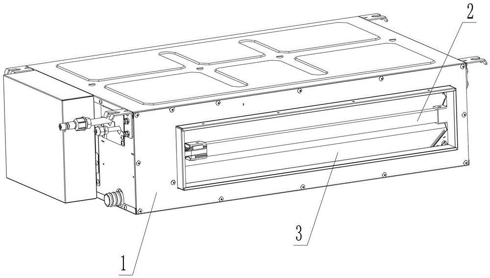
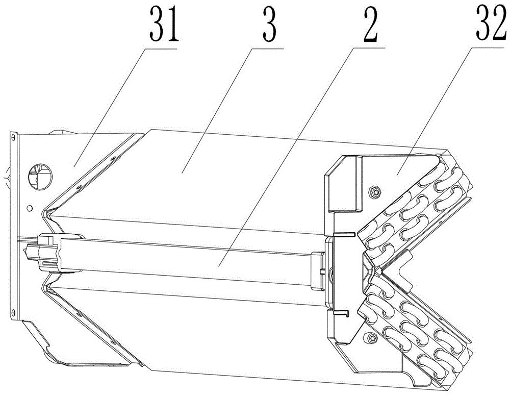
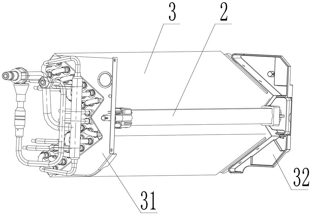
[0027] refer to Figure 1 to Figure 5 , an embodiment of the heat exchanger structure of the present invention is applied to the air conditioner indoor unit 1, the heat exchanger structure includes a heat exchanger 3, the electric heating device 2 is arranged on the heat exchanger 3, and the electric heating device 2 is an electric heating tube Or an electric heating rod, preferably PTC electric heating; the heat exchanger 3 is N folded, and is formed by sequentially connecting N heat exchanger segments, and a junction is formed between two adjacent heat exch...


PUM


Abstract

The invention discloses a heat exchanger structure. The heat exchanger structure comprises a heat exchanger; the heat exchanger is in N folds; N heat exchanger sections are sequentially connected to form into the heat exchanger; a combination position is formed between adjacent two heat exchanger sections; the N which is an integer is greater than or equal to 2; the connecting mode between the adjacent two heat exchanger sections of at least one combination position is splicing; an included angle is formed between the spliced adjacent two heat exchangers; a groove is formed between the combination position of sliced adjacent two heat exchange sections and a position which is opposite to the included angle; the heat exchanger structure also comprises an electric heating device; the electric heating device is arranged inside the groove. The heat exchanger has the advantages of integrating the heat exchanger and the electric heating device and being convenient to install and detach and being small in occupied space and high in heat exchanging efficiency and efficiently improving the electric heating efficiency and air conditioning unit performances.

Description

technical field [0001] The invention relates to the field of heat exchangers, in particular to a heat exchanger structure with electric heating. Background technique [0002] The current air conditioner often uses auxiliary electric heating when the indoor mechanism is heated. For the sake of electrical safety, the auxiliary electric heating usually uses PTC electric heating. The characteristic of PTC electric heating is that the more air volume passing through the electric heating body, the higher the performance improvement. However, the installation position of the electric heating is generally located outside the evaporator, on the air outlet frame or the air inlet frame. This setting makes the electric heating device and the evaporator separate, which takes up a lot of space, and the electric heating efficiency is low, especially for the spliced ​​two-fold evaporator or multi-fold evaporator, the position of the splicing part, There is a certain space, and the air leak...

Claims


Application Information

Patent Timeline
Patent Type & Authority Patents(China)
IPC IPC(8): F24F13/00F25B29/00
Inventor 张宝生刘玉杰蔡勃王成雷新建张正甫
Owner GREE ELECTRIC APPLIANCES INC
Why Eureka
Try Eureka