Stacked color photodisplay
a color photodisplay and color technology, applied in the field of stacking color photodisplay, can solve the problems of image deformation with time and lcds have not been popularized
- Summary
- Abstract
- Description
- Claims
- Application Information
AI Technical Summary
Benefits of technology
Problems solved by technology
Method used
Image
Examples
example 1
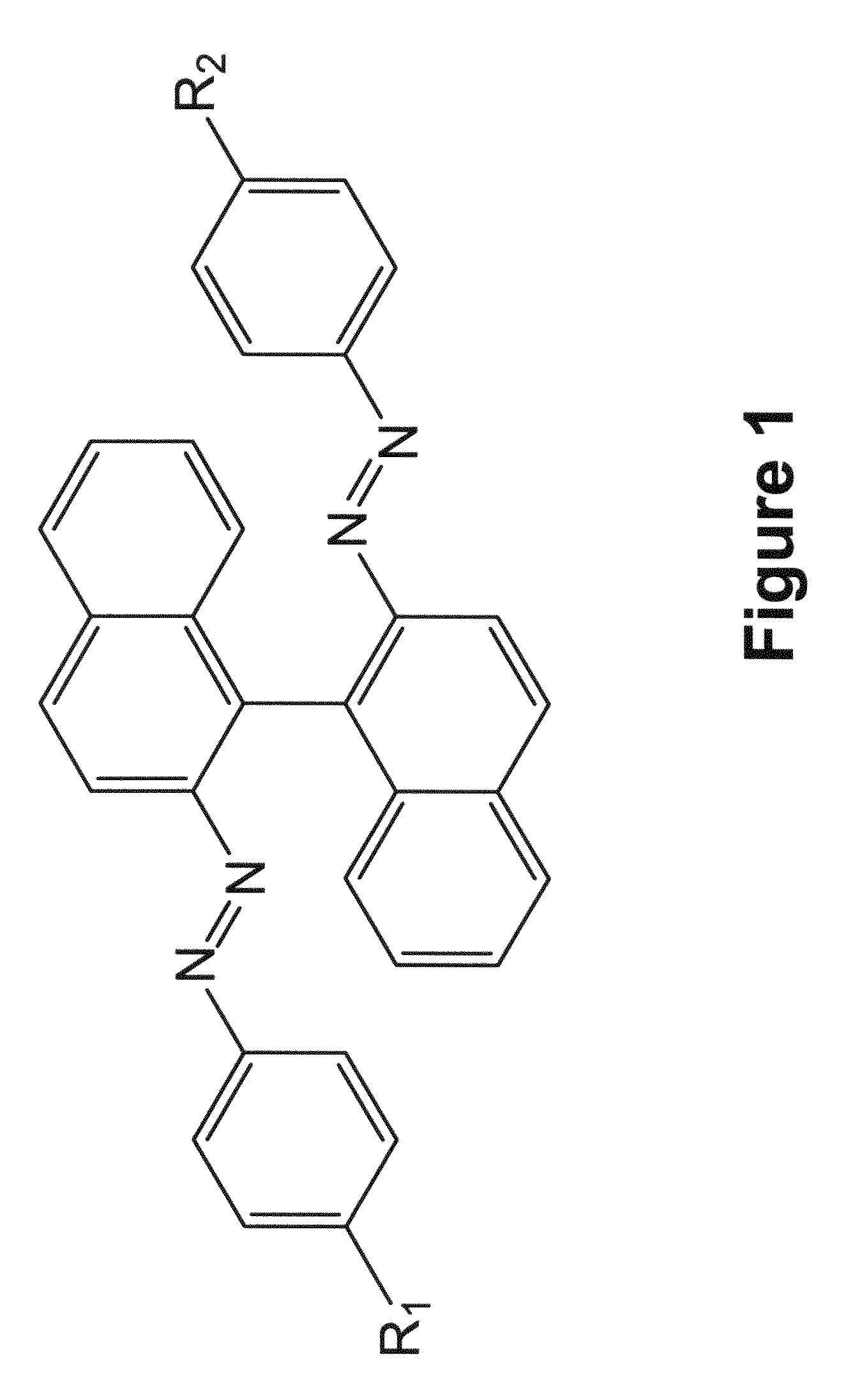
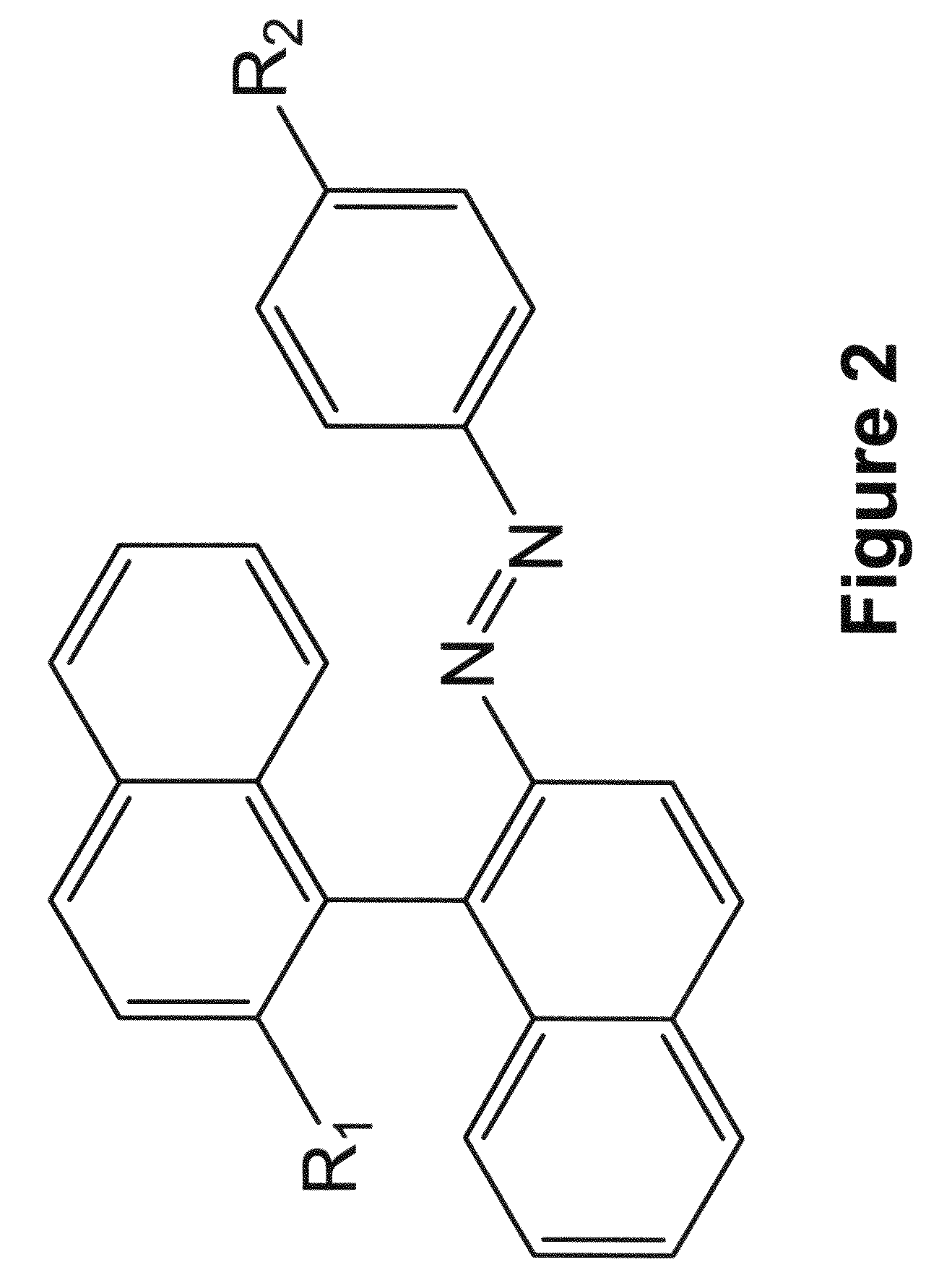
[0138]Reversible photo responsive chiral compounds of the structure diagramed in FIG. 1 with end chains: 3a) R═OC8H17, 3b) R═OC10H21, 3c) R═OC12H25, and 3d) R═OC14H29 respectively were synthesized to explore their physical characteristics for photodisplay applications. In addition reversible photo responsive chiral compounds of the structure diagramed in FIG. 2 with end chains R═CnH2n+1 (e.g. 4a R═C11H23 and 4b R═C2H5) respectively were also synthesized for comparison.
[0139]The reversible photo responsive chiral compounds were synthesized according to the following scheme.
[0140]
[0141]Synthesis of the intermediate 2:
[0142](S)-(−)-1,1′-Binaphthyl-2,2′-diamine or (R)-(+)-1,1′-binaphthyl-2,2′-diamine (1.00 g, 3.52 mmol) was dissolved in a solution of H2O (17 mL) and concentrated HCl (2.5 mL). The solution was cooled to 0° C. at ice water bath. A solution of sodium nitrite (0.58 g, 8.44 mmol) in H2O (10 mL) was dropped at ice water bath with stirring. The resulting brown yellow suspensio...
example 2
[0155]The helical twisting power, HTP, of the compounds 3a-d and 4a,b was measured by dissolving a known quantity of material in a nematic liquid crystal host and measuring the induced helical pitch length, in this case, by observing the wavelength of visible light reflected from the Bragg reflective material. The nematic host was E7, a eutectic mixture of liquid crystal components commercially available from Merck. The chiral material to be investigated was dissolved in the nematic host in sufficient quantity to form a chiral nematic material that was Bragg reflective in the visible spectrum. The HTP was measured in a display cell fabricated from two glass substrates (2 in×2 in) each coated with a transparent conductor indium tin oxide (ITO), which was over-coated with a hard coat layer and a polyimide alignment layer. The two glass pieces are held together with a gasket material and spacers to maintain a cell thickness of 5 microns. The back surface of the cell, opposite the viewi...
example 3
[0157]A fixed negative photo image was created on a display cell. The display cell was fabricated from of two glass substrates (2 in×2 in) each coated with a transparent conductor indium tin oxide (ITO), which was overcoated with a hard coat layer and a polyimide alignment layer. The two glass pieces are held together with a gasket material and spacers to maintain a cell thickness of 5 microns. A small gap is left in the gasket material to fill the cell with the photochiral liquid crystal mixture. The cell is filled in a vacuum chamber with cholesteric liquid crystal mixture consisting of 0.8% 3b (left-handed photo-chiral dopant), 15.87% E44 (nematic host, Merck), and 83.33% BLO61 (mixture of a nematic host with right-handed chiral dopant, Merck). Once filled, the cell is placed in a bladder press at 6 psi for 30 minutes to press the cell to a uniform thickness. After 30 minutes, the cell is sealed with Hardman's two-part epoxy. Once the epoxy is cured, the cell is back painted with...
PUM
 Abstract
Description
Claims
Application Information
 - R&D
- Intellectual Property
- Life Sciences
- Materials
- Tech Scout
- Unparalleled Data Quality
- Higher Quality Content
- 60% Fewer Hallucinations
Browse by: Latest US Patents, China's latest patents, Technical Efficacy Thesaurus, Application Domain, Technology Topic, Popular Technical Reports.
© 2025 PatSnap. All rights reserved.Legal|Privacy policy|Modern Slavery Act Transparency Statement|Sitemap|About US| Contact US: help@patsnap.com


