Co-molded plastic pinch clip

Active Publication Date: 2012-06-19
MERRICK ENG
View PDF4 Cites 33 Cited by
  • Summary
  • Abstract
  • Description
  • Claims
  • Application Information

AI Technical Summary

Benefits of technology

[0007]The preferred embodiment of the clip of this invention comprises a pair of jaws formed of a first, relatively hard, plastic material; a resilient spring formed of a second relatively hard, but resilient, plastic material; and a plurality of pads formed of a third, relatively soft, plastic material mounted on each of said jaws. The second plastic material has a higher tensile strength than the first plastic material. The third plastic material is softer than the other plastic materials and exhibits a higher coefficient of friction, as well. Each of the jaws is a generally planar member comprising an enlarged first end portion defining a finger grasping section with a pad of the resilient plastic material on an outer surface thereof, an intermediate portion, and a second end portion including another section with a pad of the resilient plastic material on an inner surface of the jaw member. The intermediate portions of a pair of jaws are joined together b

Problems solved by technology

However, each of these patents describes a clip which is fabricated of a relatively hard plastic material which is difficult to use because of distress to the fingers of the user and, as well, possible damage to the items, such as clothing, which are held in place by the clips.
These ridges or grooves can snag or tear the item especially, if

Method used


Image

  • Co-molded plastic pinch clip
  • Co-molded plastic pinch clip
  • Co-molded plastic pinch clip

Examples


Example

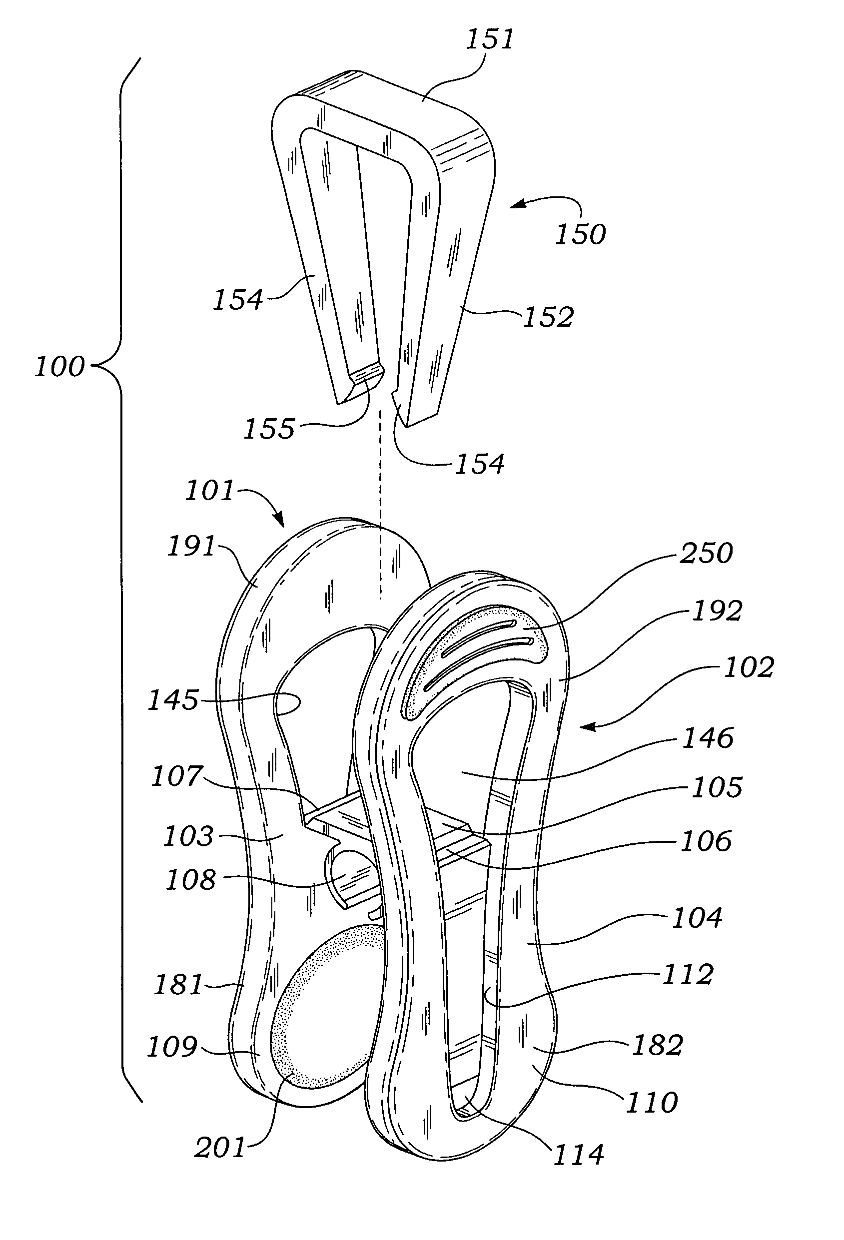
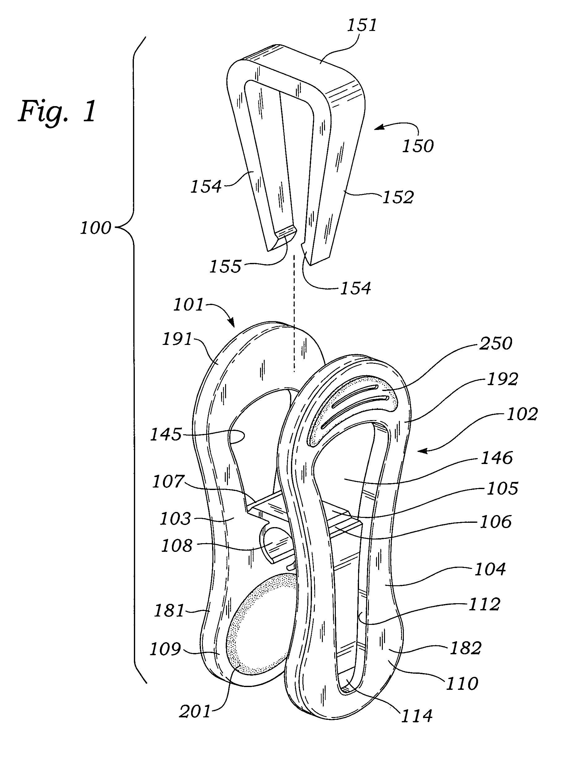
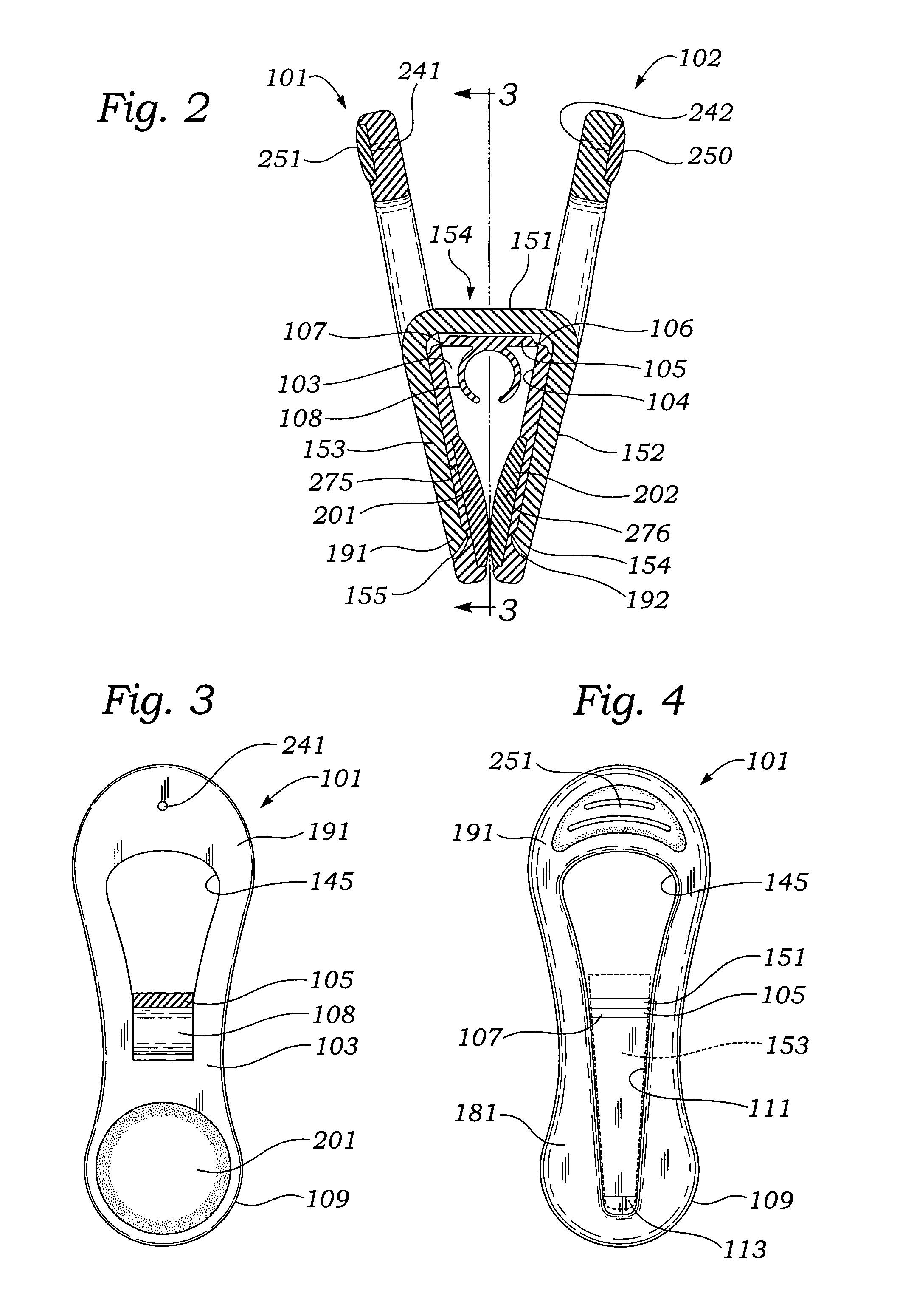
[0012]For convenience, in the several Figures, like reference characters refer to like components.

[0013]Referring concurrently to FIGS. 1 and 2, there is shown an exploded, perspective view of the clip 100 and a cross sectional view of the assembled clip, respectively. The clip 100 comprises a pair of facing, complementary jaws 101 and 102 with an intermediate bridge 105 connecting the jaws to one another. The jaws are connected to bridge 105 by living hinges 106 and 107.

[0014]In addition, arcuate recess 108 is formed on the underside of bridge 105 and is suitably configured to receive at least a portion of the periphery of a hanger arm or any other element having a circular (or cylindrical) configuration.

[0015]As can be seen in FIGS. 1 and 2, the angular extent of the arcuate recess 108 is somewhat less than 360 degrees. The gap in the arcuate recess and the relative flexibility of the segments thereof permits the recess 108 to releasably grip an external longitudinal support (not ...


PUM


Abstract

A co-molded plastic pinch clip with certain portions thereof formed from different materials. The clip is adapted to be secured to the body of a hanger, to a clothesline, or any other suitable element. The clip comprises a pair of complementary jaw members formed of a relatively hard plastic material joined together by a bridge-like member. The bridge-like member is joined, at each end, to the middle portion of each of the complementary jaw members by means of a living hinge. A substantially rigid, resilient member engages and presses against the outer surfaces of the complementary jaw members to maintain the relative positions thereof and, as well, force them into engagement at one end. Each jaw member includes a relatively soft plastic pad on the opposite sides of the opposite ends thereof such that a pair of soft plastic pads are disposed in abutting relationship at the inner engagable ends of the clip and a pair of soft plastic pads are disposed at the outer pressable ends of the clip.

Description

BACKGROUND[0001]1. Field of the Invention[0002]This invention relates, generally, to molded plastic pinch clips and, more specifically, to pinch clips with co-molded, soft plastic sections thereof for improved operation and utility.[0003]2. Prior Art[0004]Pinch clips are known in the art. For example, U.S. Pat. Nos. 4,878,276; 5,075,935; 2,471,606; inter alia, each describes a pinch clip with a resilient spring member for compressing a pair of opposed jaws. However, each of these patents describes a clip which is fabricated of a relatively hard plastic material which is difficult to use because of distress to the fingers of the user and, as well, possible damage to the items, such as clothing, which are held in place by the clips.[0005]That is, the hard plastic gripping ends of known pinch clips, typically, have ridges or grooves to ensure a secure grip on the items held by the clip. These ridges or grooves can snag or tear the item especially, if the item is a piece of clothing or ...

Claims


Application Information

Patent Timeline
IPC IPC(8): A41F1/00
CPCA47G25/48D06F55/02Y10T24/44376Y10T24/44444
Inventor ABDI, ABRAHAMABDI, MUNACOULTER, CHARLES L.
Owner MERRICK ENG
Why Eureka
Try Eureka