Backlight assembly and connector used therefor

a backlight and connector technology, applied in the direction of coupling device connection, lighting and heating apparatus, instruments, etc., can solve the problems of glass breakage, difficult removal of lamps, error, etc., and achieve the effect of improving assembly operability and low cos

Inactive Publication Date: 2012-06-19
JAPAN AVIATION ELECTRONICS IND LTD
View PDF26 Cites 3 Cited by
  • Summary
  • Abstract
  • Description
  • Claims
  • Application Information

AI Technical Summary

Benefits of technology

[0019]It is therefore a technical object of the present invention to provide a backlight assembly for a liquid crystal panel, which aims to establish electrical connection between a fluorescent tube (CCFL tube) and an inverter substrate and which is low in cost and is improved in assembling operability.Means to Solve the Problem
[0021]In the aspect of the present invention, it is preferable that, in the backlight assembly, the casing includes a sheet metal and a support base, the connector is held in a loosely-fitted state by the sheet metal and the support base, the first connecting portion includes a pair of spring portions, and the pair of spring portions have a shape which enables positioning of the fluorescent tube.

Problems solved by technology

However, the connector shown in Patent Document 2 requires a parts cost for a holder cap and a coupling plate.
It is assumed that a θ error occurs during mounting of the connector and during fixing of a substrate.
This may possibly cause glass breakage.
Further, when the lamp is replaced, removal of the lamp becomes difficult and, therefore, it is inevitable to replace other parts also.
With this structure, a parts cost for the cap and an operation of fitting the cap are added.
Accordingly, correction of a positioning error between the substrate and the fluorescent tube is difficult.
In addition, designing and assembling processes are difficult.
This process requires many-hours, resulting in a high cost.Patent Document 1: JP-A-2004-294592Patent Document 2: JP-A-2006-344602Patent Document 3: JP-A-2000-123604

Method used


Image

  • Backlight assembly and connector used therefor
  • Backlight assembly and connector used therefor
  • Backlight assembly and connector used therefor

Examples


first embodiment

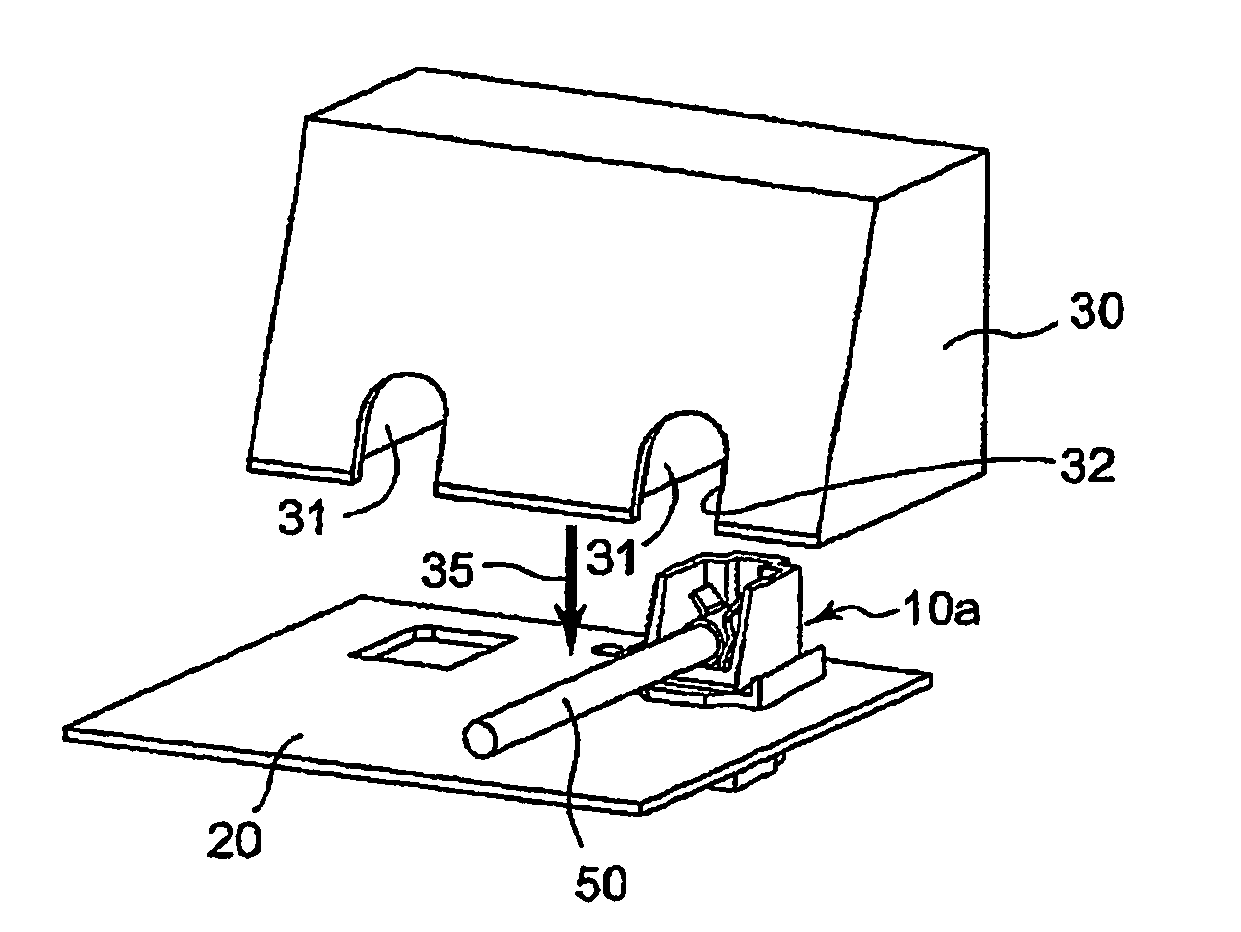
[0071]Referring to FIG. 7, a connector 10a according to a first embodiment of the present invention has a housing 1 formed of an insulating material having a high thermal resistance (approximately 160° C.) in view of heat buildup of an electrode portion of a lamp 52, and a metal contact 2 having an excellent conductivity. The metal contact 2 is used for connection between a fluorescent tube (CCFL tube) 50 and an inverter substrate 40 (see FIGS. 13, 14, and 15). The fluorescent tube 50 has one end which is inserted into one end of the contact. As will later be described, the inverter substrate 40 is inserted into an insertion opening 4 opened at a lower portion of the connector so as to be brought into contact with the other end of the contact.

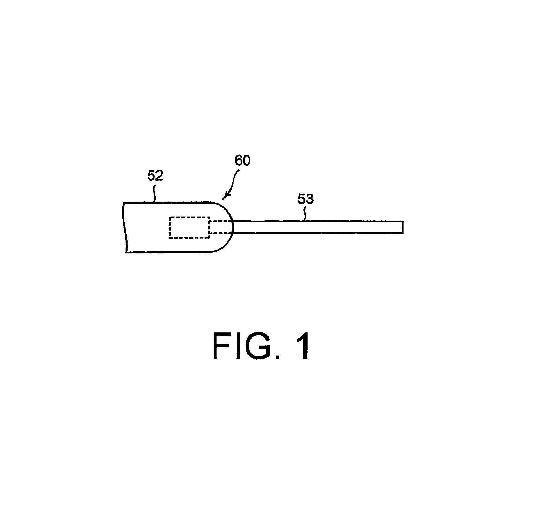
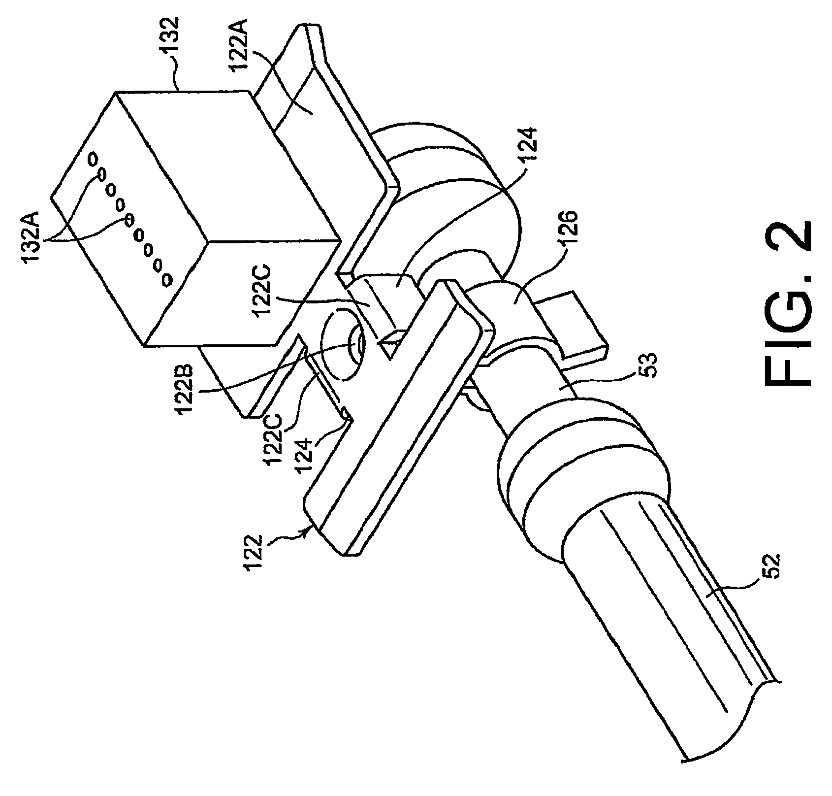
[0072]Referring to FIG. 8, the fluorescent tube 50 comprises the lamp 52, a Dumet wire 53 led out from the inside of the lamp 52, and a ferrule 51 formed of a metal cap having a U-shaped section and covering one end of the lamp 52 as a connecti...

second embodiment

[0097]Referring to FIG. 16 and FIG. 17 (a)-(d), a connector 10b according to a second embodiment of the present invention has the housing 1 formed of an insulating material having a high thermal resistance (approximately 160° C.) in view of heat buildup of an electrode portion of the lamp 52, and the metal contact 2 having an excellent conductivity. The metal contact 2 is used for connection between the fluorescent tube (CCFL tube) 50 and the inverter substrate 40 (see FIGS. 13, 14, and 15). The fluorescent tube 50 has one end which is inserted into the contact. As will later be described, the inverter substrate 40 is inserted into the insertion opening 4 opened at a lower portion of the connector so as to be brought into contact with the other end of the contact.

[0098]The contact 2 is similar in structure to that described in connection with FIG. 9 (a), (b).

[0099]The housing 1 of the connector 10b according to the second embodiment of the present invention is different from that of...


PUM


Abstract

To provide a backlight assembly for a liquid crystal panel, which aims to establish electrical connection between a fluorescent tube (CCFL tube) and an inverter substrate and which is low in cost and improved in assembling operability. A connector 10a includes a contact 2 and a housing 1 holding the contact 2. The contact 2 includes a holding portion held by the housing 1, a first connecting portion 18 connected to a connecting portion 51 of the fluorescent tube, and a second connecting portion 19 connected to the substrate. The first connecting portion 18 is formed from one end of the holding portion through a floating portion. The second connecting portion 19 is formed from the other end of the holding portion.

Description

CROSS REFERENCE TO RELATED APPLICATIONS[0001]This application is the National Stage of PCT / JP2008 / 061191 filed on Jun. 19, 2008, which claims priority under 35 U.S.C. §119 of Japanese Application No. 2007-163396 filed on Jun. 21, 2007. The international application under PCT article 21(2) was not published in English.TECHNICAL FIELD[0002]This invention relates to a backlight connector and a backlight assembly using the same and, in detail, to a backlight connector for a liquid crystal panel of a liquid crystal television or the like, and a backlight assembly using the same.BACKGROUND ART[0003]Conventionally, a fluorescent tube used in a backlight of the type includes a lamp formed of a glass tube and a Dumet wire led out from an electrode of the lamp.[0004]As a connector used for connection of the conventional fluorescent tube, there are known connectors shown in Patent Documents 1 and 2.[0005]A lamp connecting member (connector) disclosed in Patent Document 1 comprises a contact fi...

Claims


Application Information

Patent Timeline
Patent Type & Authority Patents(United States)
IPC IPC(8): G09F13/04
CPCH01R33/02G02F1/133604F21V19/00H01R13/426G02F1/1335
Inventor NAITO, TAKEHARU
Owner JAPAN AVIATION ELECTRONICS IND LTD
Why Eureka
Try Eureka