Antenna device for mobile communication system

a mobile communication system and antenna device technology, applied in the field of mobile communication systems, can solve the problems of difficult to find an installation site for the antenna device, high cost is another obstacle to the placement of the antenna device, and the site is difficult to secure, so as to facilitate the securing of the installation site

Active Publication Date: 2012-06-19
KMW INC
View PDF8 Cites 230 Cited by
  • Summary
  • Abstract
  • Description
  • Claims
  • Application Information

AI Technical Summary

Benefits of technology

[0010]An aspect of exemplary embodiments of the present invention is to address at least the problems and / or disadvantages and to provide at least the advantages described below. Accordingly, an aspect of exemplary embodiments of the present invention is to provide an antenna device for a mobile communication system, which can be installed in a place where an existing street lamp or a surveillance camera is installed in order to facilitate securing of an installation site.
[0012]A further aspect of exemplary embodiments of the present invention provides an antenna device for a mobile communication system to reduce the number of posts used for module installation by enabling installation of a lamp module for a street lamp, a surveillance camera module, and various sensor modules to one post.

Problems solved by technology

Although the antenna device for the mobile communication system should be installed at an appropriate position to enable reliable wireless communications, such a site is hard to secure because the antenna device is considered as an obstacle to a living environment and thus building owners typically do not want antenna equipment installed.
Therefore, it is difficult to find an installation site for the antenna device.
Especially in an urban area where people make mobile calls frequently, high cost is another obstacle to the siting of the antenna device.
Accordingly, there are too many unnecessary and disfiguring posts in downtown or urban environments.

Method used


Image

  • Antenna device for mobile communication system
  • Antenna device for mobile communication system
  • Antenna device for mobile communication system

Examples


Embodiment Construction

[0021]The matters defined in the description such as a detailed construction and elements are provided to assist in a comprehensive understanding of exemplary embodiments of the invention. Accordingly, those of ordinary skill in the art will recognize that various changes and modifications of the embodiments described herein can be made without departing from the scope and spirit of the invention. Also, descriptions of well-known functions and constructions are omitted for clarity and conciseness.

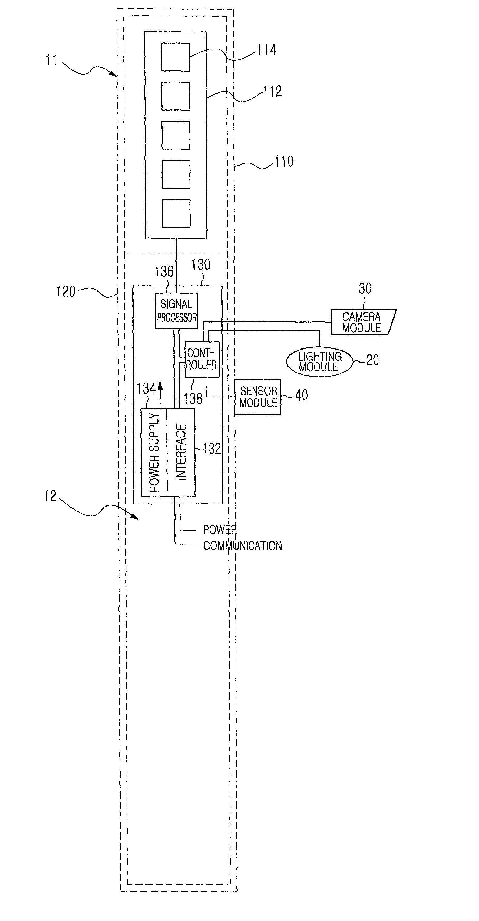
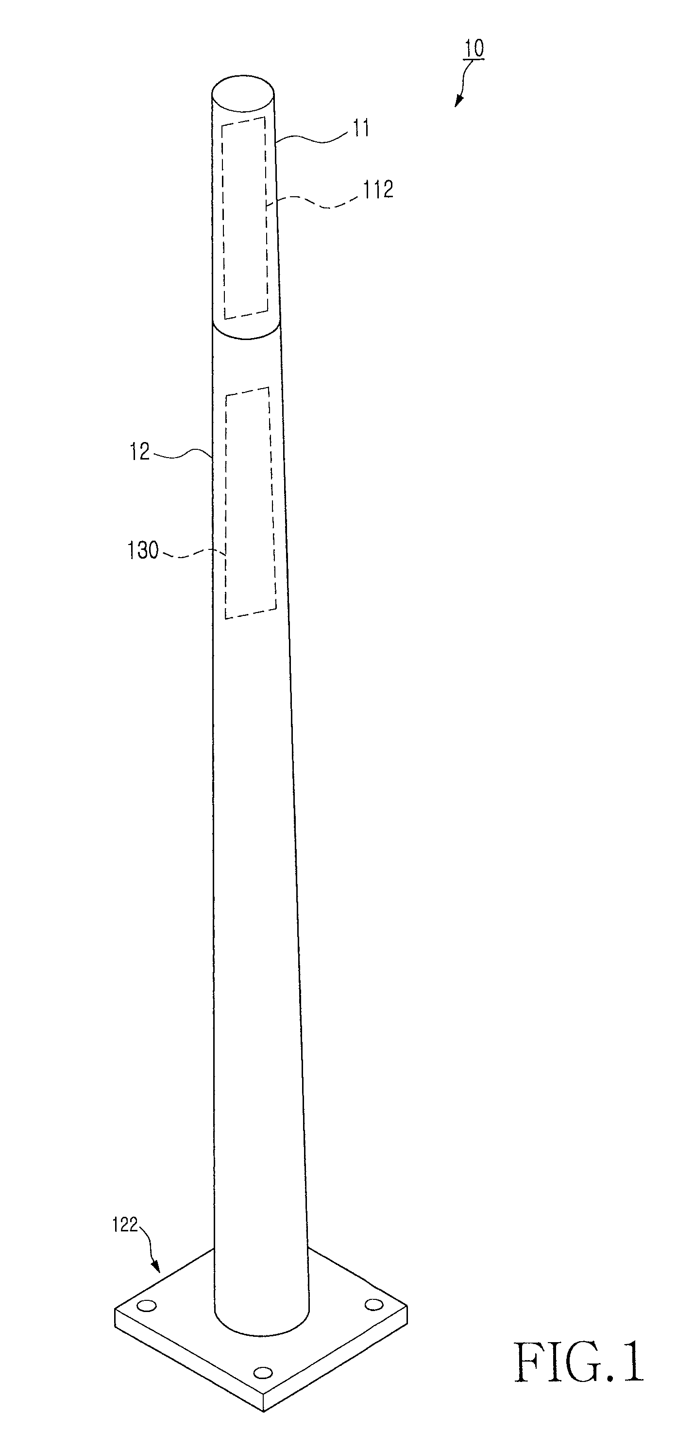
[0022]FIG. 1 is an exterior perspective view of a mobile communication antenna device according to an exemplary embodiment of the present invention.

[0023]Referring to FIG. 1, a mobile communication base station (BS) antenna device 10 according to an exemplary embodiment of the present invention takes the external overall form of a conventional lamp, utility, or sign post or pole. In the illustrated case of FIG. 1, the post-shaped BS antenna device 10 may include an antenna end 11 at an uppe...


PUM


Abstract

An antenna device for a mobile communication system is provided, in which a post has a selected external appearance. An antenna end is formed at an upper portion of the post for installing antenna parts, and a support end is formed at a lower portion of the post for fixing the antenna device to the ground. At least part of an external body of the antenna end is formed of a material that transmits transmission and received radio signals and a ground support member is formed under the support end to make an external body of the support end stand erect on the ground. The external appearance of the antenna device may take the form of a conventional utility, lamp, or sign post or pole.

Description

CLAIM OF PRIORITY[0001]This application claims the benefit under 35 U.S.C. §119(a) of a Korean Utility Model Application filed in the Korean Intellectual Property Office filed on Mar. 10, 2009 and assigned Serial No. 20-2009-0002724, the entire disclosure of which is hereby incorporated by reference.BACKGROUND OF THE INVENTION[0002]1. Field of the Invention[0003]The present invention generally relates to a mobile communication system. More particularly, the present invention relates to an antenna device for a Base Station (BS) in a mobile communication system.[0004]2. Description of the Related Art[0005]In a mobile communication system, a BS (including a Relay Station (RS)) typically collects data from Mobile Stations (MSs) via their connections and transmits the collected data to a switching network. The BS amplifies a transmission signal through a high-power amplifier within a BS body, transmits the amplified signal to an antenna device, and radiates it through the antenna device....

Claims


Application Information

Patent Timeline
Patent Type & Authority Patents(United States)
IPC IPC(8): H01Q1/12
CPCH01Q1/246H01Q1/42H01Q1/44H01Q21/08F21S13/10H01Q1/1207
Inventor KIM, DUK-YONG
Owner KMW INC
Why Eureka
Try Eureka