
Wireless communication interface for portable wireless terminal

a wireless terminal and wireless communication technology, applied in the field of portable wireless terminals, can solve the problems of difficult to intuitively check communication security, difficult to secure a radio link, and difficulty in communicating with high speed and driving with low power, and achieve the effect of easy securing a radio link, low power, and high speed

Inactive Publication Date: 2012-06-19
SAMSUNG ELECTRONICS CO LTD
View PDF17 Cites 32 Cited by
  • Summary
  • Abstract
  • Description
  • Claims
  • Application Information

AI Technical Summary

Benefits of technology

The present invention provides a wireless communication interface for a portable wireless terminal that allows for intuitive checking of communication security, easy securing of a radio link, high-speed communication, and low-power driving. The interface includes a light source for generating a data-modulated visible light signal and outputting it to the free space, an optical detector for converting the visible light signal into an electrical signal, and a demodulation unit for extracting the data signal. Additionally, the interface can also include a first light source for generating a data-modulated infrared signal and outputting it to the free space, a second light source for generating a visible light signal with a larger divergence angle, an optical detector for converting the infrared signal into an electrical signal, and a demodulation unit for extracting the data signal.

Problems solved by technology

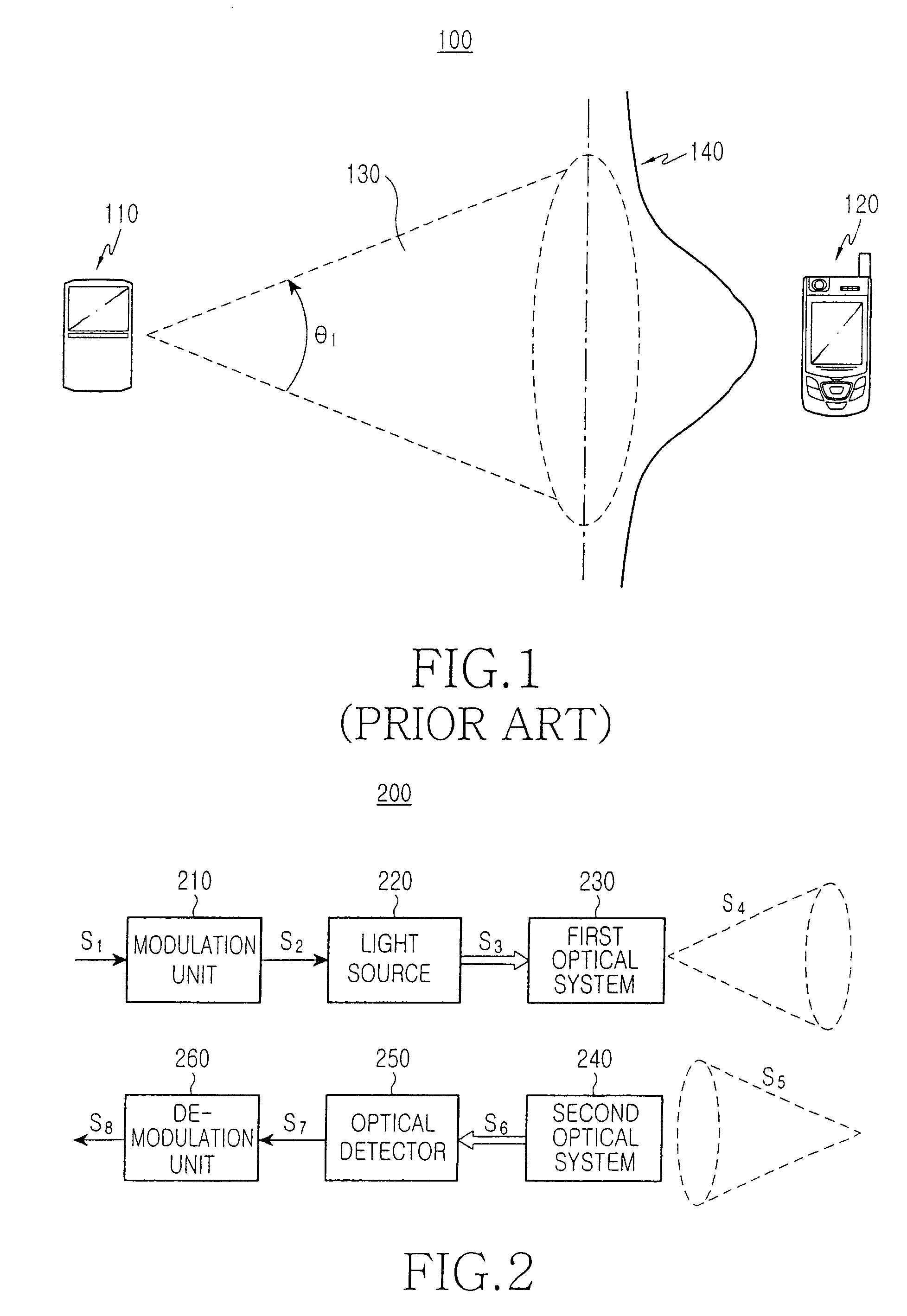
However, one of the drawbacks of the aforementioned infrared communication system 100 as described is that infrared rays are not visible to the human eye, and thus there is difficulty to intuitively check communication security, and to secure a radio link.
Also, due to the large divergence angle of an infrared signal, the infrared communication system 100 has difficulties in communicating with high speed and driving with low power.

Method used


Image

  • Wireless communication interface for portable wireless terminal
  • Wireless communication interface for portable wireless terminal
  • Wireless communication interface for portable wireless terminal

Examples


Embodiment Construction

[0020]Hereinafter, embodiments of the present invention will be described in detail with reference to the accompanying drawings. For the purposes of clarity and simplicity, a detailed description of known functions and configurations incorporated herein may be omitted to avoid obscuring the subject matter of the present invention with unnecessary descriptions of known functions and configurations. A person of ordinary skill in the art understand that the exemplary drawings and their associated descriptions are presented for illustrative purposes, and that the invention is not limited to the examples shown and described herein.

[0021]FIG. 2 is a block diagram illustrating the configuration of a wireless communication interface for a portable wireless terminal according to a first exemplary embodiment of the present invention. The wireless communication interface 200 supports the portable wireless terminal which wirelessly communicates with another device via a free space. The wireless...


PUM


Abstract

A wireless communication interface for a portable wireless terminal and a system for wirelessly communicating by a portable wireless terminal with another device via a free space. The interface facilitates aligning the portable wireless device with another devices for improved communication. The interface including: a light source for generating a data-modulated visible light signal and outputting the visible light signal to the free space; an optical detector for generating an electrical signal by photoelectrically converting the visible light signal input from the free space, and for outputting the electrical signal. A demodulation unit demodulates the electrical signal input from the optical detector, and outputs a data signal.

Description

CLAIM OF PRIORITY[0001]This application claims priority from an application entitled “Wireless Communication Interface For Portable Wireless Terminal,” filed with the Korean Intellectual Property Office on Oct. 31, 2006 and assigned Serial No. 2006-106045, the contents of which are incorporated herein by reference in its entirety.BACKGROUND OF THE INVENTION[0002]1. Field of the Invention[0003]The present invention relates to a portable wireless terminal. More particularly, the present relates to a wireless communication interface for a portable wireless terminal, which wirelessly communicates with other devices via a free space.[0004]2. Description of the Related Art[0005]In the field of a portable wireless terminals used for communications, such as a cellular phone or a personal digital assistant (PDA), and in the field of hand-held electronics such as a digital camera or an mp3 player, research has already been performed on a peripheral interface which provides communication betwe...

Claims


Application Information

Patent Timeline
Patent Type & Authority Patents(United States)
IPC IPC(8): H04B1/38H04B10/10
CPCH04M1/7253H04M1/22H04M1/72412H04B1/40H04B10/00
Inventor SHIN, DONG-JAEJUNG, DAE-KWANGSHIN, HONG-SEOKLEE, HYUNG-WOOPARK, SUNG-BUMHYUN, YOO-JEONGHYUN, LEGAL REPRESENTATIVE, SEONG HOON
Owner SAMSUNG ELECTRONICS CO LTD
Learn More