Geometrical properties measuring device for a medical treatment device including an RFID transponder

a technology of geometric properties and measuring devices, applied in the field of automatic verification, calibration and surveying instruments, can solve the problems of poor manageability, inability to match model data to possibly defective instruments in verification, and inability to accurately represent the relationship between the actual instrument and the anatomical structure to be treated, etc., to achieve the effect of reducing time and increasing process reliability

Active Publication Date: 2012-06-26
BRAINLAB
View PDF10 Cites 410 Cited by
  • Summary
  • Abstract
  • Description
  • Claims
  • Application Information

AI Technical Summary

Benefits of technology

[0012]A method and device for verifying, calibrating and surveying instruments for computer-assisted surgery are advantageously provided. The method and device provide increased reliability in processes and time reduction when employing navigated instruments for surgical procedures. Applicability of the device and method is not limited to symmetrical or otherwise geometrically simple navigable instruments, but rather instruments with complex geometries can be prepared for use in computer-assisted surgery.

Problems solved by technology

When the stored geometric data, which mainly describe the functional elements of the instrument in relation to the reference device, deviate from the actual geometry of the instrument (e.g., after the instrument has been damaged), then an incorrect representation of the relationship between the actual instrument and the anatomical structure to be treated may be produced.
Matching model data to the possibly defective instrument is not possible in verification.
Visibility problems and occasionally poor manageability when simultaneously positioning the instrument and the aid tend to extend the operation time.
Here, too, the visibility and manageability problems described above have a negative effect on the operation time.
However, this method is not currently employed since suitable aids are not available, nor could the required procedures be carried out within a reasonable time frame.
Instrument calibration can lose its validity in the course of time.
This can be caused by attrition or by being mechanically burdened once or repeatedly.

Method used


Image

  • Geometrical properties measuring device for a medical treatment device including an RFID transponder
  • Geometrical properties measuring device for a medical treatment device including an RFID transponder
  • Geometrical properties measuring device for a medical treatment device including an RFID transponder

Examples


Embodiment Construction

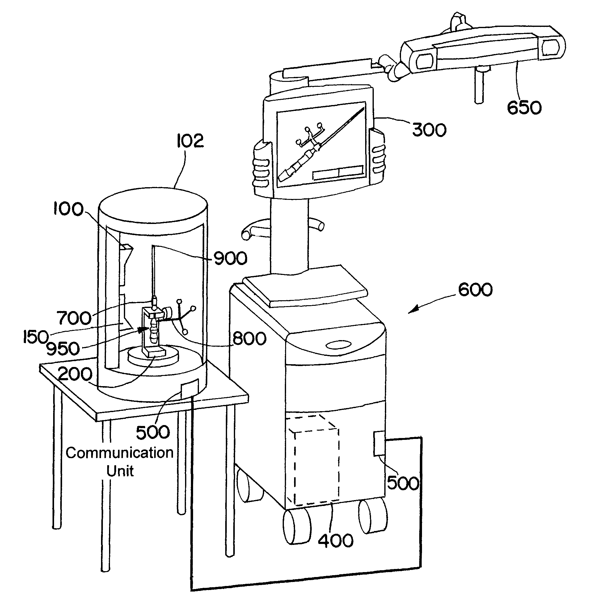
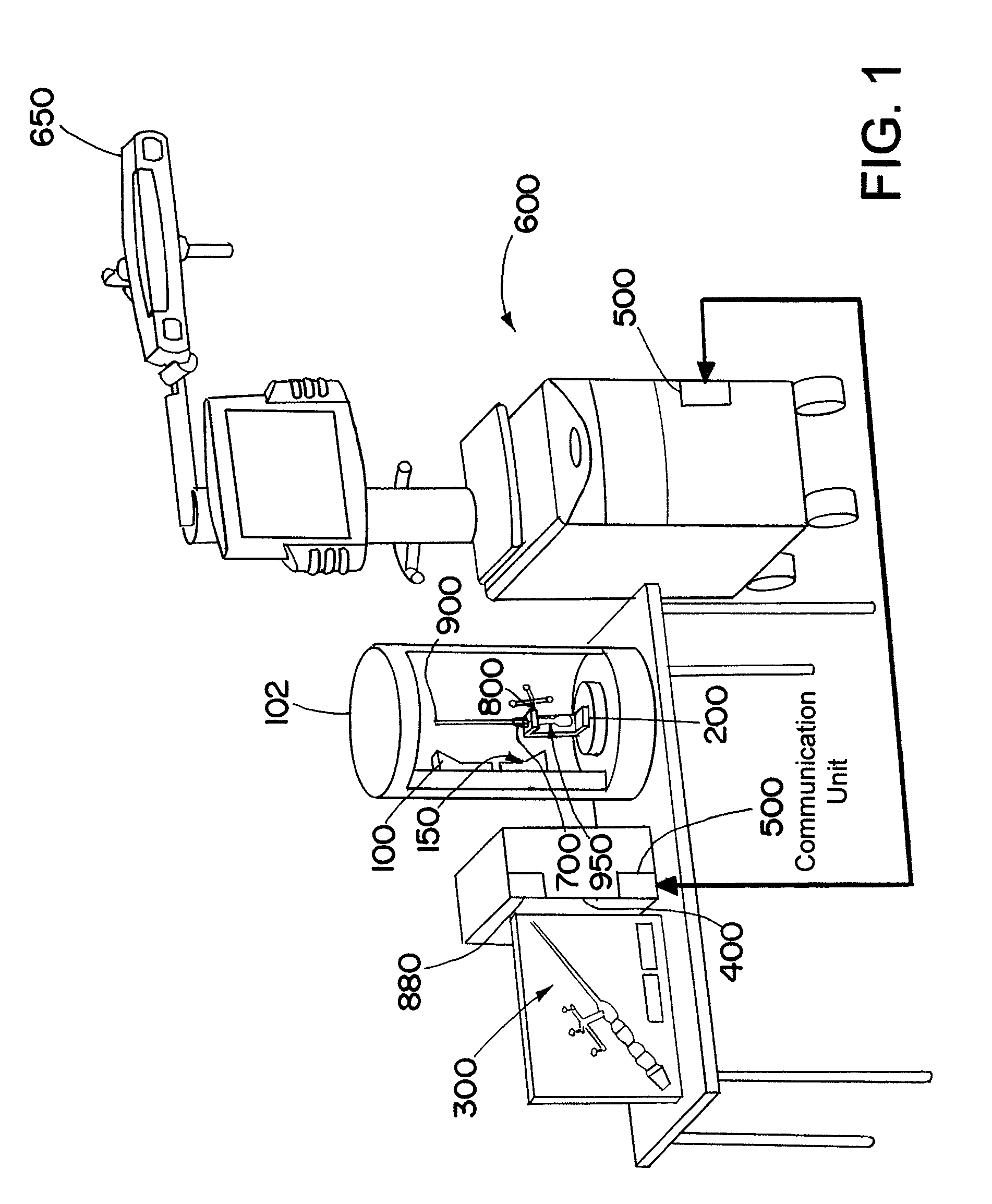
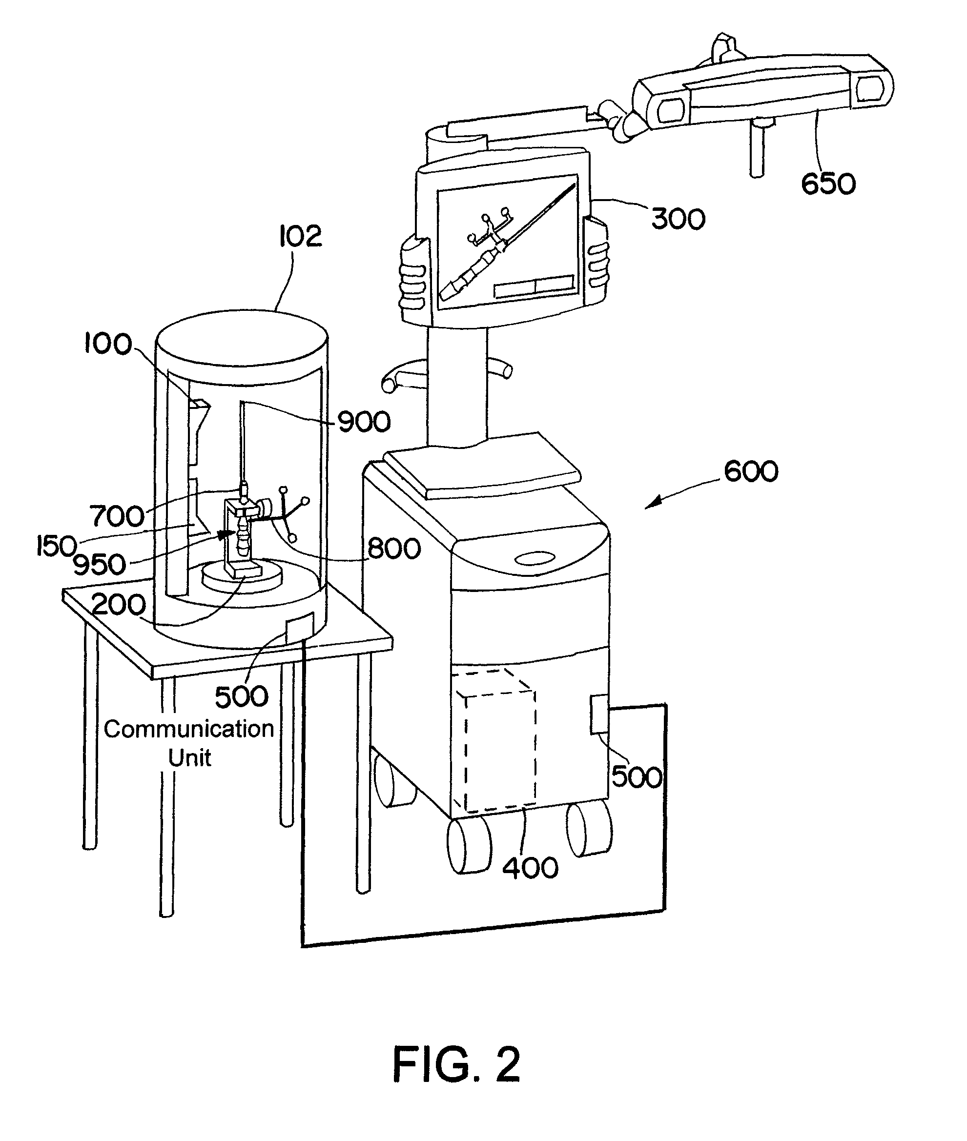
[0058]FIG. 1 illustrates an exemplary embodiment in accordance with the present invention, wherein a scanning device 100 and an instrument holding unit 200 are arranged in a cylindrical casing 102. An infrared camera unit 150 also can be attached in the casing 102 in order to check the condition, shape or quality of active or passive markers. The check can be performed, for example, by emitting infrared radiation onto the markers and, via the infrared camera unit 150, detecting the reflected infrared radiation. Alternatively, the infrared camera unit 150 can detect infrared radiation emitted by the markers. In the present example, an instrument 700 is positioned within the casing 102, preferably fixedly or non-movably in the instrument holding unit 200, wherein a reference system 800 is attached to the instrument 700 and the instrument 700 comprises an instrument tip 900 as a functional element. An RFID transponder 950 is located in the interior of the instrument 700 and / or the refe...


PUM


Abstract

A measuring device for measuring geometric properties of a medical treatment device includes a measuring unit, a time detection unit, and an RFID writer. The measuring unit is configured to measure a relative position between at least a first part of the medical treatment device and at least a second part of the medical treatment device. The time detection unit configured to detect a time of the measurement, and the RFID writer configured to write a time, based on the detected time, to an RFID transponder of the medical treatment device.

Description

RELATED APPLICATION DATA[0001]This application claims priority of U.S. Provisional Application No. 60 / 826,973 filed on Sep. 26, 2006, which is incorporated herein by reference in its entirety.FIELD OF THE INVENTION[0002]The present invention relates to a device and method for measuring geometric properties of medical treatment devices. More particularly, the invention relates to automatically verifying, calibrating and surveying instruments for use in computer-assisted surgery, wherein the geometry of the instrument and of a reference system can be ascertained as a three-dimensional model with the aid of optical scanning methods.BACKGROUND OF THE INVENTION[0003]In computer-assisted operations, the position and orientation of surgical instruments relative to the patient's anatomical structures can be represented to the surgeon with the aid of a navigation system (e.g., on a display device of the navigation system). In addition to the anatomical structures, the instruments used during...

Claims


Application Information

Patent Timeline
Patent Type & Authority Patents(United States)
IPC IPC(8): G08B21/00
CPCA61B19/46A61B19/52A61B19/5244A61B19/56A61B2019/448A61B2019/461A61B2019/4815A61B2019/502A61B2019/5251A61B2019/5255A61B2019/566A61B2034/102A61B90/36A61B2034/2055A61B2034/256A61B34/20A61B34/25A61B90/98A61B90/06A61B2090/061A61B2090/0803A61B2034/2051
Inventor NEUBAUER, TIMOPLA.BETA.KY, NORMANMILLAHN, MANUEL
Owner BRAINLAB
Why Eureka
Try Eureka