Swivel seat with adjustable swivel resistance

a swivel seat and adjustable technology, applied in the direction of lifting devices, vehicle components, vehicle arrangements, etc., can solve the problem of limited rotation ability of the operator's sea

Active Publication Date: 2012-07-03
CROWN EQUIP CORP
View PDF19 Cites 11 Cited by
  • Summary
  • Abstract
  • Description
  • Claims
  • Application Information

AI Technical Summary

Benefits of technology

[0008]The swivel mechanism may be supported on a base structure of the seat. Conveniently, the adjustable resistance control may be arranged such that at least a portion extends through the base structure. In this way, the adjustable resistance control can be readily operated on the fly by a vehicle operator supported on the seat bottom.
[0009]Suitably, the adjustable resistance control comprises a plunger, lever or other member that is engageable with the second member or otherwise causes the second member to move relative to the first member thus changing the force being exerted against the first member and, hence, the resistance to movement of the first member. By way of example, the plunger may be movable towards and away from the second member, so as to adjust the resistance between the first and second members. In one beneficial arrangement, the adjustable resistance control comprises a rotatable knob configured such that rotation of the knob in a first direction causes a plunger to extend from the adjustable resistance control so as to cause the second member to pivot generally towards the first member thus increasing the force required to swivel the operator's seat, and rotation of the knob in a second direction opposite the first direction allows the second member to pivot generally away from the first member thus decreasing the force required to swivel the operator's seat.

Problems solved by technology

In this regard, the ability of the operator's seat to rotate may be limited, e.g., by the physical constraints of the operator's compartment, by the positioning of the control elements, and / or by the necessity of the operator to engage in different seated positions.

Method used


Image

  • Swivel seat with adjustable swivel resistance
  • Swivel seat with adjustable swivel resistance
  • Swivel seat with adjustable swivel resistance

Examples


Embodiment Construction

[0023]In the following description of the preferred embodiments, reference is made to the accompanying drawings that form a part hereof, and in which is shown by way of illustration, and not by way of limitation, specific preferred embodiments in which the invention may be practiced. It is to be understood that other embodiments may be utilized and that changes may be made without departing from the spirit and scope of the present invention. In particular, the features described with reference to a particular figure should not be considered as being limited only to that specific embodiment but may be incorporated into or exchanged with other features, unless otherwise stated.

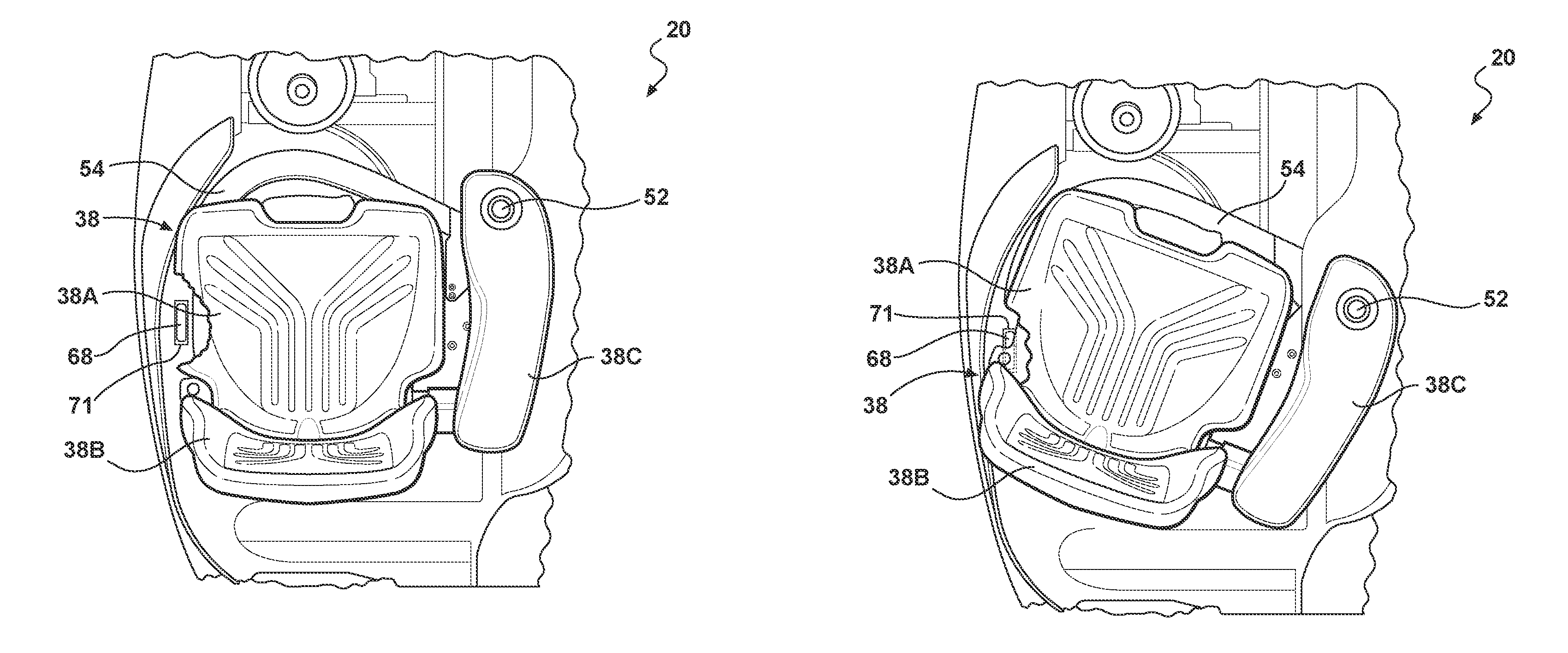
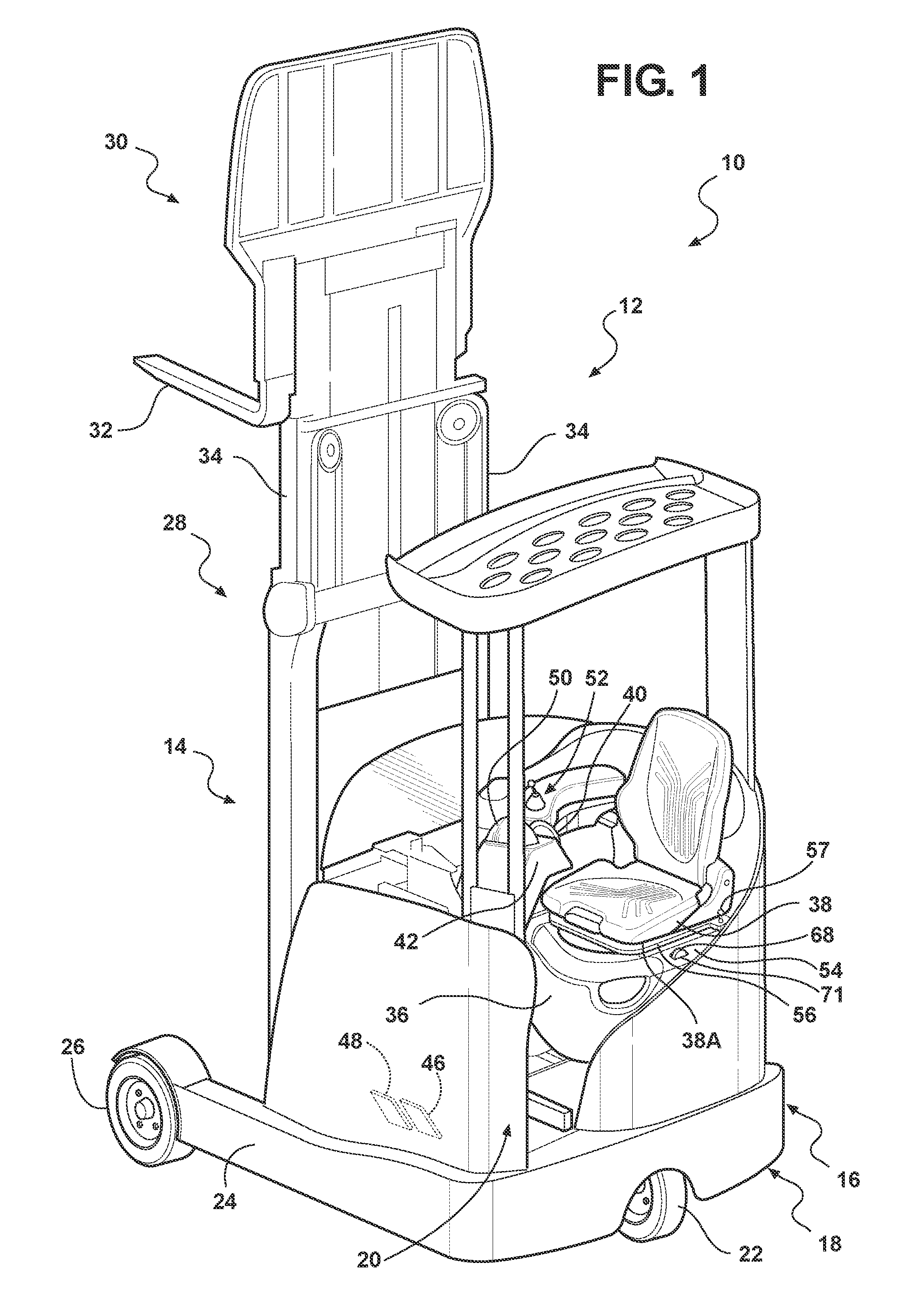
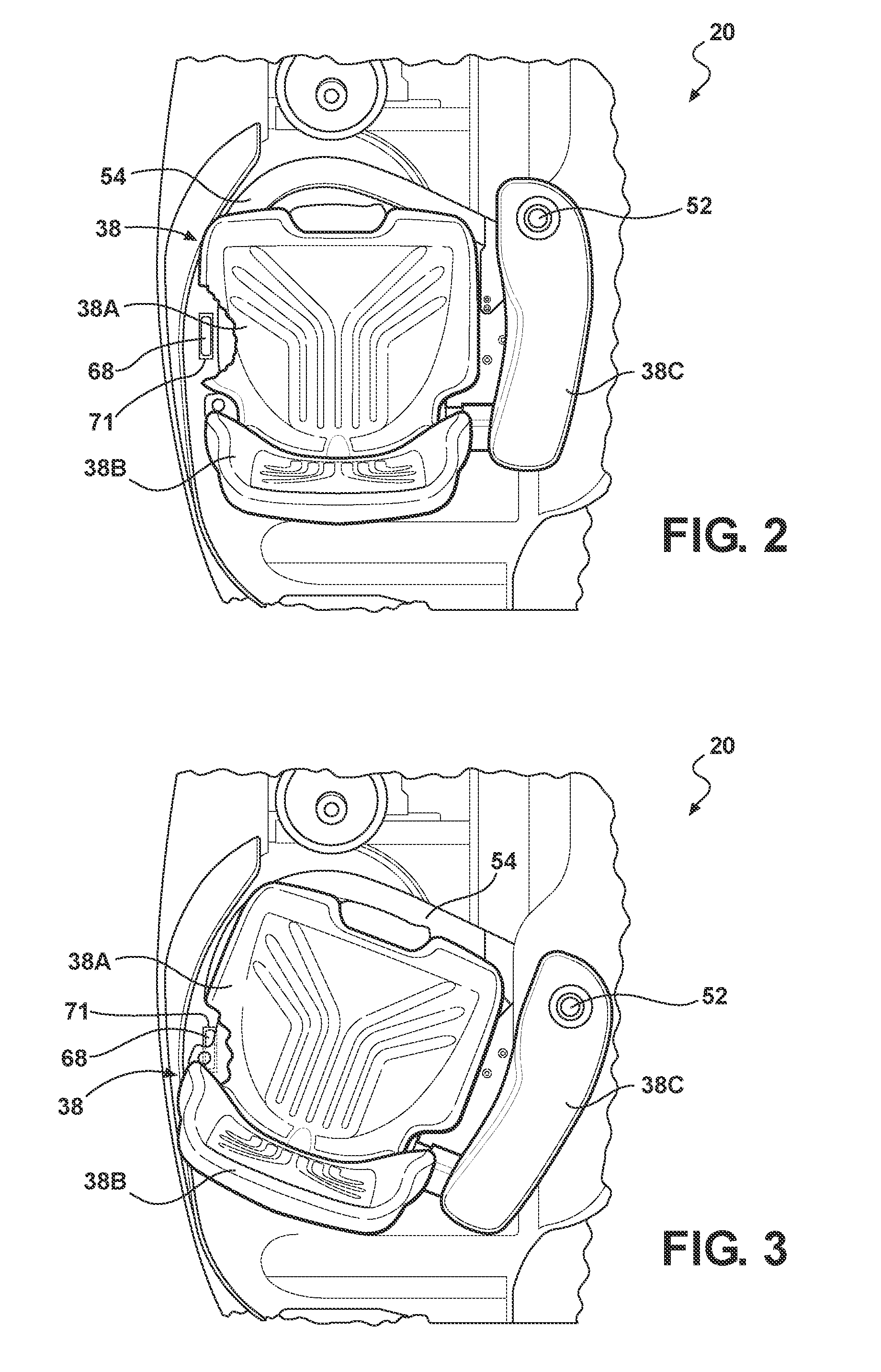
[0024]According to various aspects of the present invention, an operator's seat for a materials handling vehicle includes a capability to rotate / swivel. Moreover, the vehicle operator has the ability to adjust the amount of rotation resistance exhibited by the operator's seat, e.g., “on the fly”, so that the ope...


PUM


Abstract

A swiveling seat comprises a seat bottom, a swivel mechanism and a swivel resistance system. The swivel mechanism allows the seat bottom to rotate at least partially around a first axis of rotation. The swivel resistance system may include a first member that rotates with the swivel mechanism, a second member that is fixedly positioned relative to the swiveling of the swivel mechanism and an operator adjustable resistance control that is operated by the vehicle operator to bias the second member into the first member so as to vary the resistance required to swivel the operator's seat.

Description

APPLICATION INCORPORATED BY REFERENCE[0001]This application claims the benefit of U.S. Provisional Application No. 61 / 098,928, filed Sep. 22, 2008 and entitled “SWIVEL SEAT WITH ADJUSTABLE SWIVEL RESISTANCE,” the disclosure of which is incorporated by reference herein.BACKGROUND OF THE INVENTION[0002]The present invention relates in general to seats for materials handling vehicles, and more particularly, to systems and methods for integrating adjustable resistance features with swiveling seats for materials handling vehicles. The present invention further relates to swivel seats with adjustable resistance capabilities and materials handling vehicles having swiveling seats with adjustable resistance capabilities.[0003]Materials handling vehicles typically include a platform, cab or other form of operator's compartment having an operator's seat and a number of control elements located in the vicinity of the seat within reach of the hands and / or feet of a corresponding vehicle operator...

Claims


Application Information

Patent Timeline
Patent Type & Authority Patents(United States)
IPC IPC(8): A47C1/00B60N2/75
CPCB60N2/14B60N2/24B66F9/0759B66F9/07545B60N2/4693B60N2/797
Inventor ADELSPERGER, PETERBABEL, CHRISTOPHHOISS, MICHAELKRAIMER, JAMES V.
Owner CROWN EQUIP CORP
Why Eureka
Try Eureka