Radar imaging system and method using second moment spatial variance

a spatial variance and radar technology, applied in the field of radar systems, can solve the problems of affecting the performance of the same radar, the inability of the same radar to autonomously distinguish stationary ground vehicles from background clutter, and the inability to achieve the effect of detecting background clutter,

Active Publication Date: 2012-07-03
RAYTHEON CO
View PDF41 Cites 6 Cited by
  • Summary
  • Abstract
  • Description
  • Claims
  • Application Information

AI Technical Summary

Problems solved by technology

While the ability of SAR radars to produce better and better imagery advances, the ability of those same radars to autonomously distinguish stationary ground vehicles from background clutter remains difficult.
These two layers of processing are performed before the template processing is applied, since the template based processing can be easily overwhelmed with a high false alarm rate.
Another problem of template based target identification is that its performance is based on prior knowledge of the target.
One drawback of template based target detection methods is that small variations in target configurations can reduce the effectiveness of the templates.
Also, since a SAR image contains many small scatters whose physical size is on the order of the radar's wavelength, constructive and destructive interference of the complex returns produces phenomena called speckle, which reduces image quality and decreases probability of target detection.
However, these approaches remain inadequate for current more demanding applications.

Method used


Image

  • Radar imaging system and method using second moment spatial variance
  • Radar imaging system and method using second moment spatial variance
  • Radar imaging system and method using second moment spatial variance

Examples


Embodiment Construction

[0016]Illustrative embodiments and exemplary applications will now be described with reference to the accompanying drawings to disclose the advantageous teachings of the present invention.

[0017]While the present invention is described herein with reference to illustrative embodiments for particular applications, it should be understood that the invention is not limited thereto. Those having ordinary skill in the art and access to the teachings provided herein will recognize additional modifications, applications, and embodiments within the scope thereof and additional fields in which the present invention would be of significant utility.

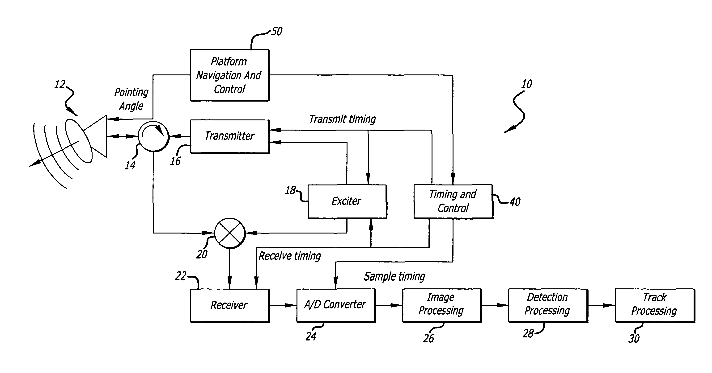
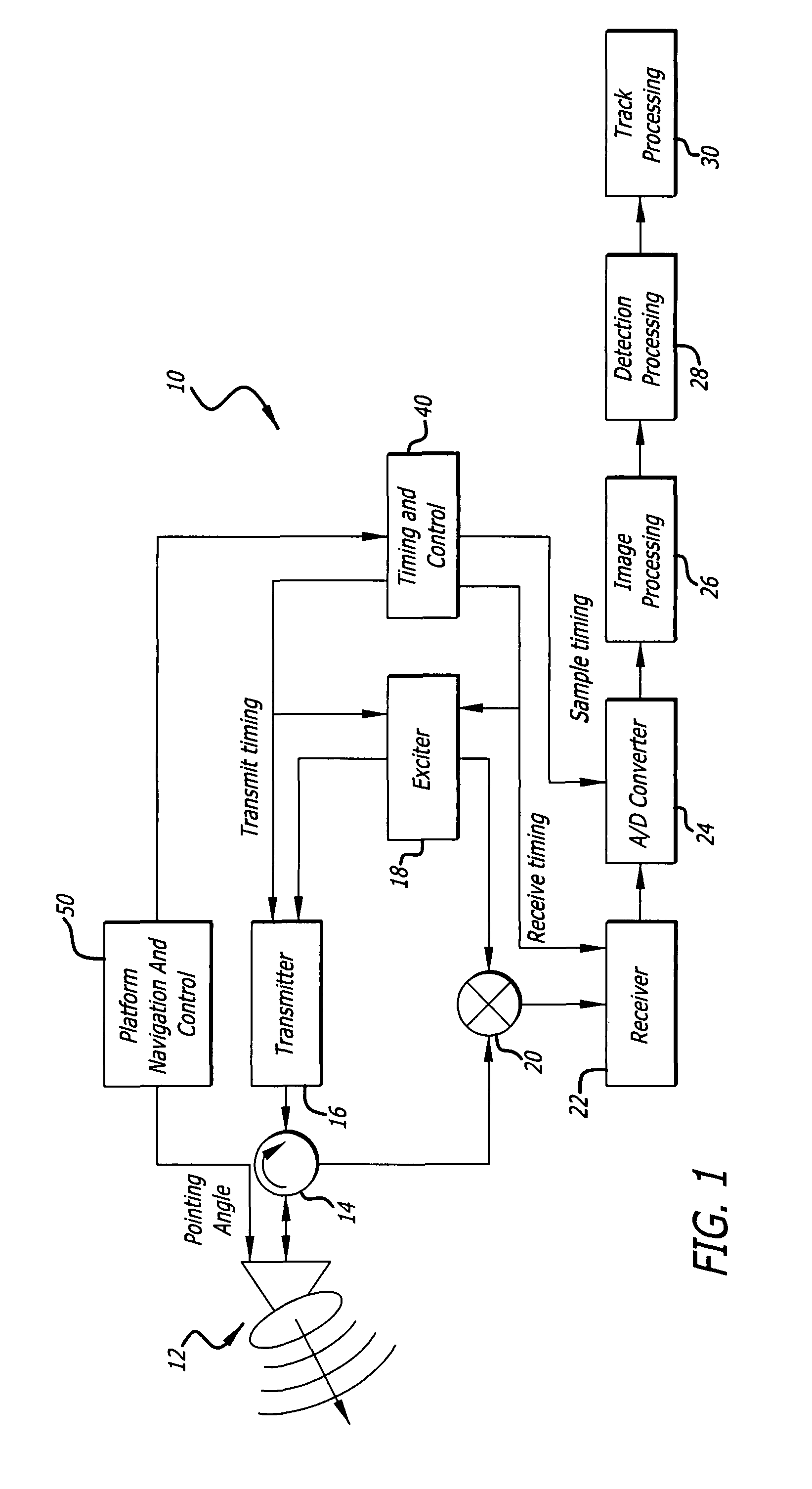
[0018]The present invention exploits a recognition that for complex targets viewed from airborne radar, a high degree of scene variance can provide better detection of a fluctuating target than amplitude based detection methods. This alternative method of distinguishing targets from background is presented that can be used instead of, or in conjuncti...


PUM


Abstract

A detection system and method. The inventive system includes an arrangement for receiving a frame of image data; an arrangement for performing a variance calculation with respect to at least one pixel in the frame of image data; and an arrangement for comparing the calculated variance with a predetermined threshold to provide output data. In the illustrative embodiment, the frame of image data includes a range / Doppler matrix of N down range samples and M cross range samples. In this embodiment, the arrangement for performing a variance calculation includes an arrangement for calculating a variance over an N×M window within the range / Doppler matrix. The arrangement for performing a variance calculation includes an arrangement for identifying a change in a standard deviation of a small, localized sampling of cells. In accordance with the invention, the arrangement for performing a variance calculation outputs a variance pixel map.

Description

REFERENCE TO COPENDING APPLICATIONS[0001]This application claims the benefit of United States Provisional Application No. 60 / 854,776, filed Oct. 26, 2006, the disclosure of which is hereby incorporated by reference. In addition, copending patent applications entitled RADAR IMAGING SYSTEM AND METHOD USING DIRECTIONAL GRADIENT MAGNITUDE SECOND MOMENT SPATIAL VARIANCE DETECTION and RADAR IMAGING SYSTEM AND METHOD USING GRADIENT MAGNITUDE SECOND MOMENT SPATIAL VARIANCE DETECTION, both filed Oct. 18, 2007 by D. P. Bruyere et al., Ser. Nos. 11 / 975,391, now U.S Pat. No. 7,830,300, and 11 / 975,393, now U.S. Pat. No. 8,054,217, involve second moment gradient magnitude detection and directional gradient second moment detection, respectively, the teachings of which are hereby incorporated herein by reference.BACKGROUND OF THE INVENTION[0002]1. Field of the Invention[0003]The present invention relates to radar systems and associated methods. More specifically, the present invention relates to sy...

Claims


Application Information

Patent Timeline
Patent Type & Authority Patents(United States)
IPC IPC(8): G01S13/89G01S13/90G01S13/00
CPCG01S7/411G01S13/9035G01S13/9027
Inventor BRUYERE, DONALD P.ASHCRAFT, IVAN S.TREECE, JOHN B.
Owner RAYTHEON CO
Why Eureka
Try Eureka