

Multiphase grid synchronized regulated current source inverter systems
a current source inverter and multi-phase grid technology, applied in ac network circuit arrangements dc-ac conversion without reversal, etc., can solve the problem of pva representing a dc source with a degree of unpredictability in terms of output stability, requiring high-speed semiconductor devices that are limited, and affecting the magnitude of dc output voltage. the effect of three-phase current total harmoni
- Summary
- Abstract
- Description
- Claims
- Application Information
AI Technical Summary
Benefits of technology
Problems solved by technology
Method used
Image

Examples
example no.1
Example No. 1
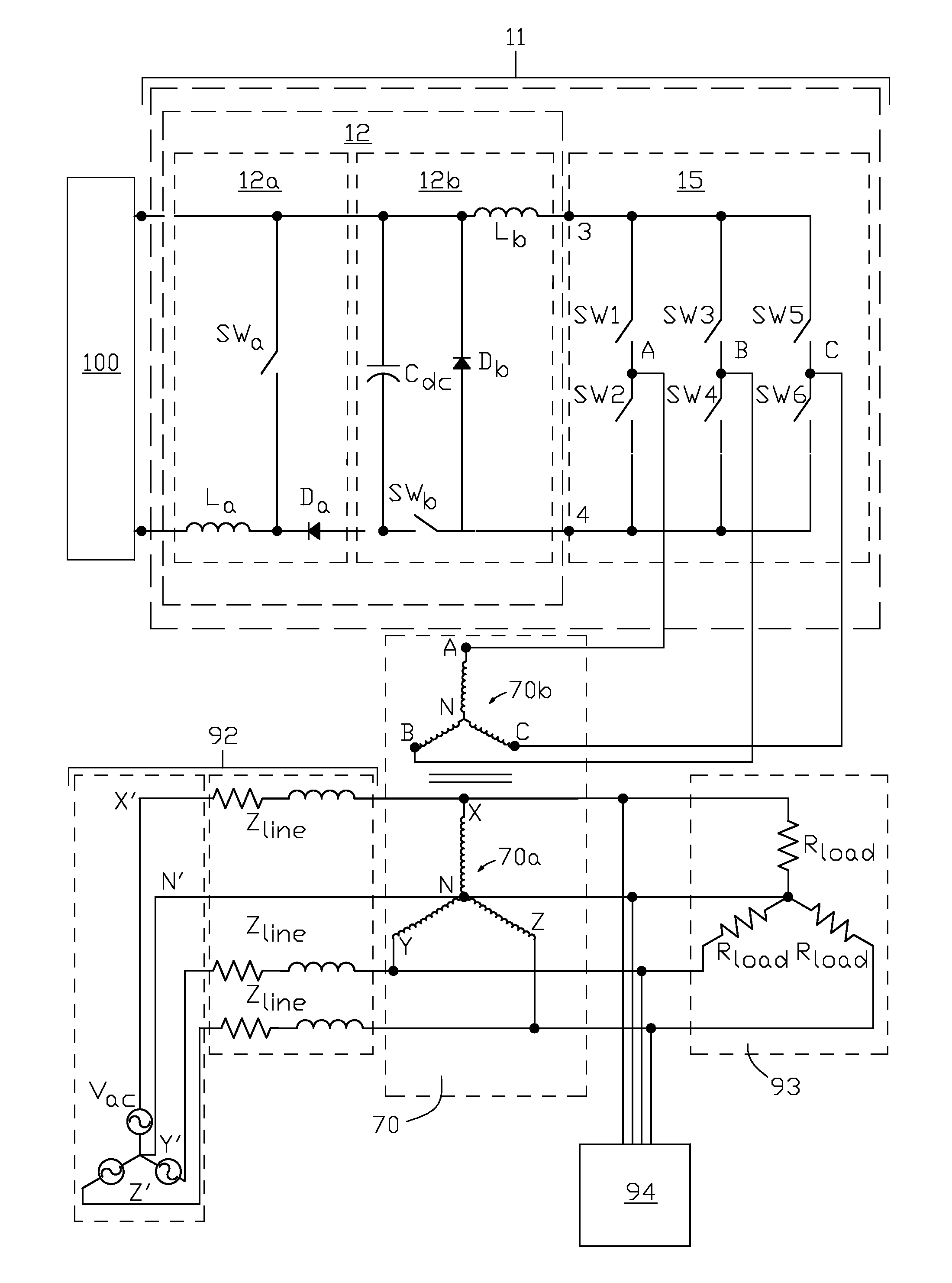
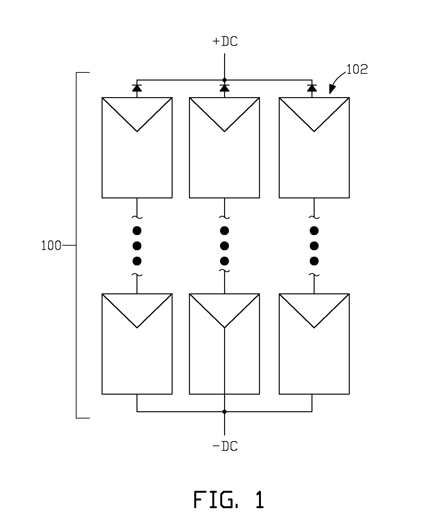
[0086]FIG. 9 illustrates one example of a multiphase grid synchronized regulated current source inverter system of the present invention wherein RCSI 11 inverter section 15 outputs three phase power that undergoes a wye-wye transformation in transformer 70 before being injected into the grid. Regulator section 12 of the RCSI comprises step-up dc current regulator subsection 12a and step-down dc current regulator subsection 12b, which is supplied current from the plurality of dc sources 100 and outputs regulated dc current to the input (points 3 and 4) of three phase inverter 15. The ac outputs (labeled A, B and C in FIG. 9) of this inverter are connected to the wye-configured secondary windings 70b of transformer 70. The wye-configured primary windings 70a of transformer 70 are connected to three phase power grid 92. Grid 92 is schematically represented by lumped line impedances Zline and grid power sources Vac. Current supplied to the grid feeds loads 93, which are con...
example no.2
Example No. 2
[0096]FIG. 13 illustrates another example of a multiphase grid synchronized regulated current source inverter system of the present invention wherein a six phase RCSI system has its output connected to transformer 72 that has branched wye-configured secondary windings. The six phase RCSI system comprises two, three phase regulated current source inverters 11 and 11′, each of which is connected to the six phase secondary windings of transformer 72. First three phase RCSI 11 comprises dc current regulator section 12 and three phase inverter section 15, with plurality of dc sources 100 providing input dc power to RCSI 11. AC outputs A, B and C of inverter 15 are connected to terminals A, B, and C of the secondary windings of transformer 72 as shown in FIG. 13. Similarly second three phase RCSI 11′ comprises dc current regulator section 12′ and three phase inverter section 15′, with plurality of dc sources 100′ providing input dc power to the RCSI 11′. AC outputs R, S and T...
example no.3
Example No. 3
[0108]FIG. 17 illustrates another example of a multiphase grid synchronized regulated current source inverter system of the present invention wherein a nine phase RCSI system has its output connected to transformer 74 that has branched wye-configured secondary windings. The nine phase RCSI system can be used to provide greater output power with a lower THD value than that achieved with the six phase RCSI system described above. The nine phase RCSI system comprises three, three phase RCSI 11, 11′ and 11″, each of which has its output connected to the nine phase secondary windings of transformer 74. First three phase RCSI 11 comprises dc current regulator section 12 and three phase inverter section 15, with plurality of dc sources 100 providing input dc power to RCSI 11. AC outputs A, B and C of inverter 15 are connected to terminals A, B, and C of the secondary windings of transformer 74 as shown in FIG. 17. Similarly second three phase RCSI 11′ comprises dc current regu...
PUM
 Abstract
Description
Claims
Application Information