Beverage container receptacle and method of installing the same

a beverage container and receptacle technology, applied in the field of receptacles, can solve the problems of insufficient stability of the beverage container and the limited size of the receptacle, and achieve the effect of facilitating its mounting and better bearing the weight of the holding

Inactive Publication Date: 2012-07-10
THIRD HAND MARKETING
View PDF25 Cites 7 Cited by
  • Summary
  • Abstract
  • Description
  • Claims
  • Application Information

AI Technical Summary

Benefits of technology

[0005]The beverage container receptacle herein described is adapted for installation relative to fixed first and second structures, and provides a stable rest for securely holding a beverage container. It further facilitates its mounting on a free, horizontally projecting end portion of the fixed first structure, or on an intermediate portion extending horizontally between two unsuitable mounting locations on the fixed first structure. It is to be understood that the fixed first and second structures referred to herein may be portions of a common structure, and need only be fixed relative to each other. The fixed first structure may be, for example, the exposed valve and piping arrangement of a urinal or toilet; the fixed second structure may be, for example, the wall on which the urinal is mounted or which lies behind the toilet. Its supporting engagement with the second structure permits the receptacle to better bear the weight of the held beverage container.

Problems solved by technology

Typically, prior such receptacles merely clip onto the valve assembly or related pipes, and lack a desired level of sturdiness, which results in their supporting the beverage container in an inadequately stable manner.
Additionally, prior such receptacles are typically limited to being mounted at only a single position or to only one particular component of the valve and piping arrangement.

Method used


Image

  • Beverage container receptacle and method of installing the same
  • Beverage container receptacle and method of installing the same
  • Beverage container receptacle and method of installing the same

Examples


Embodiment Construction

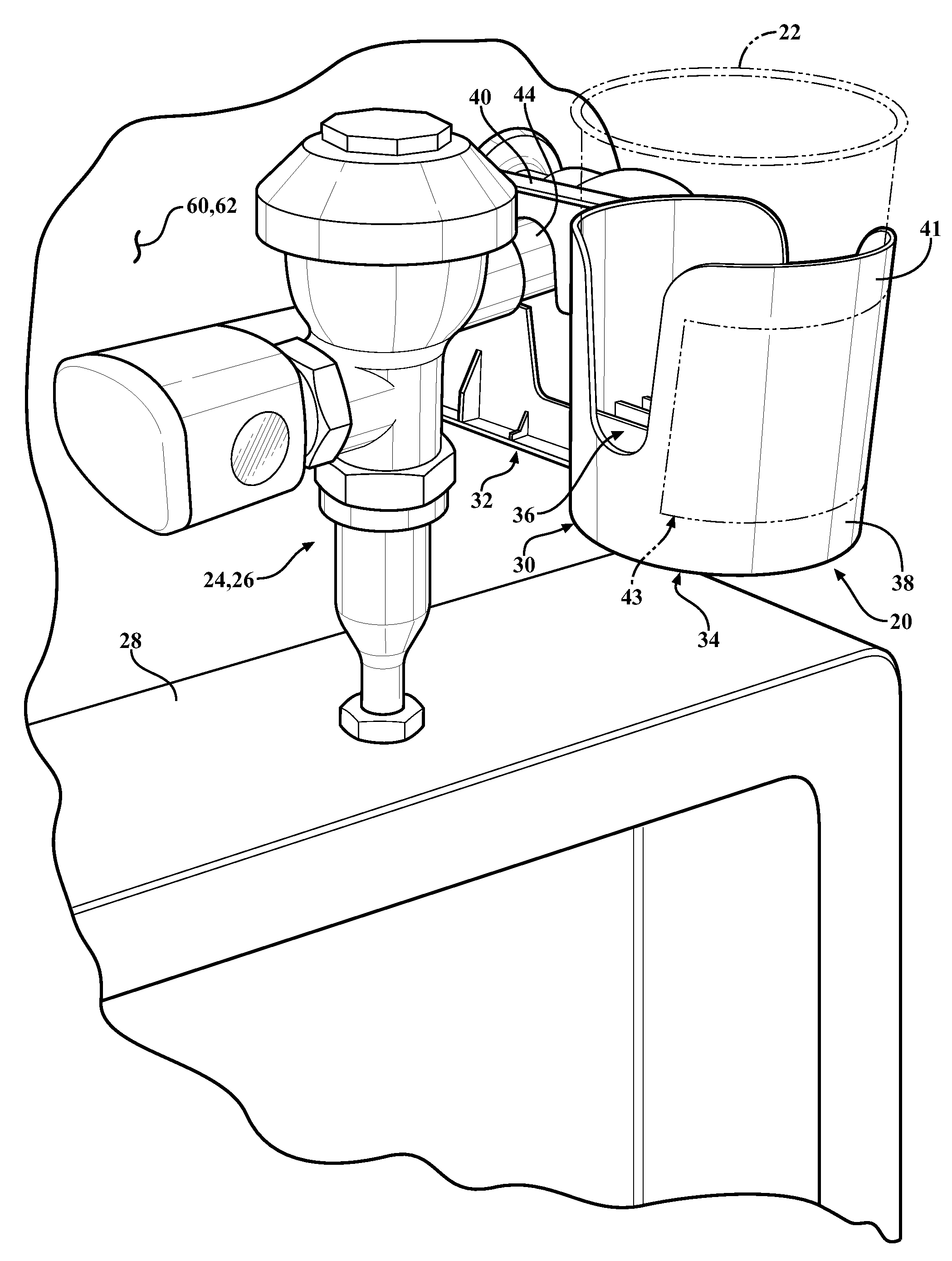
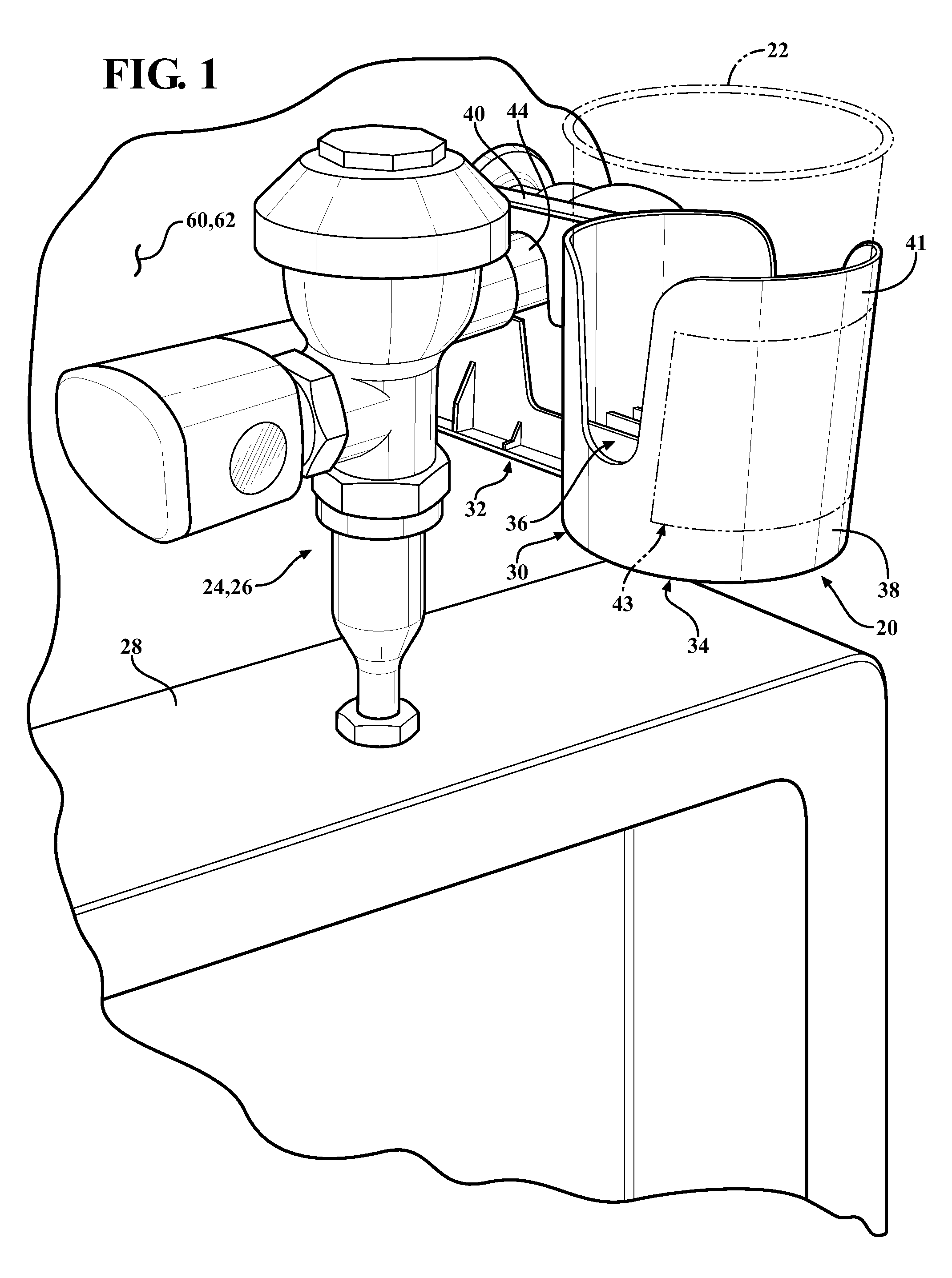
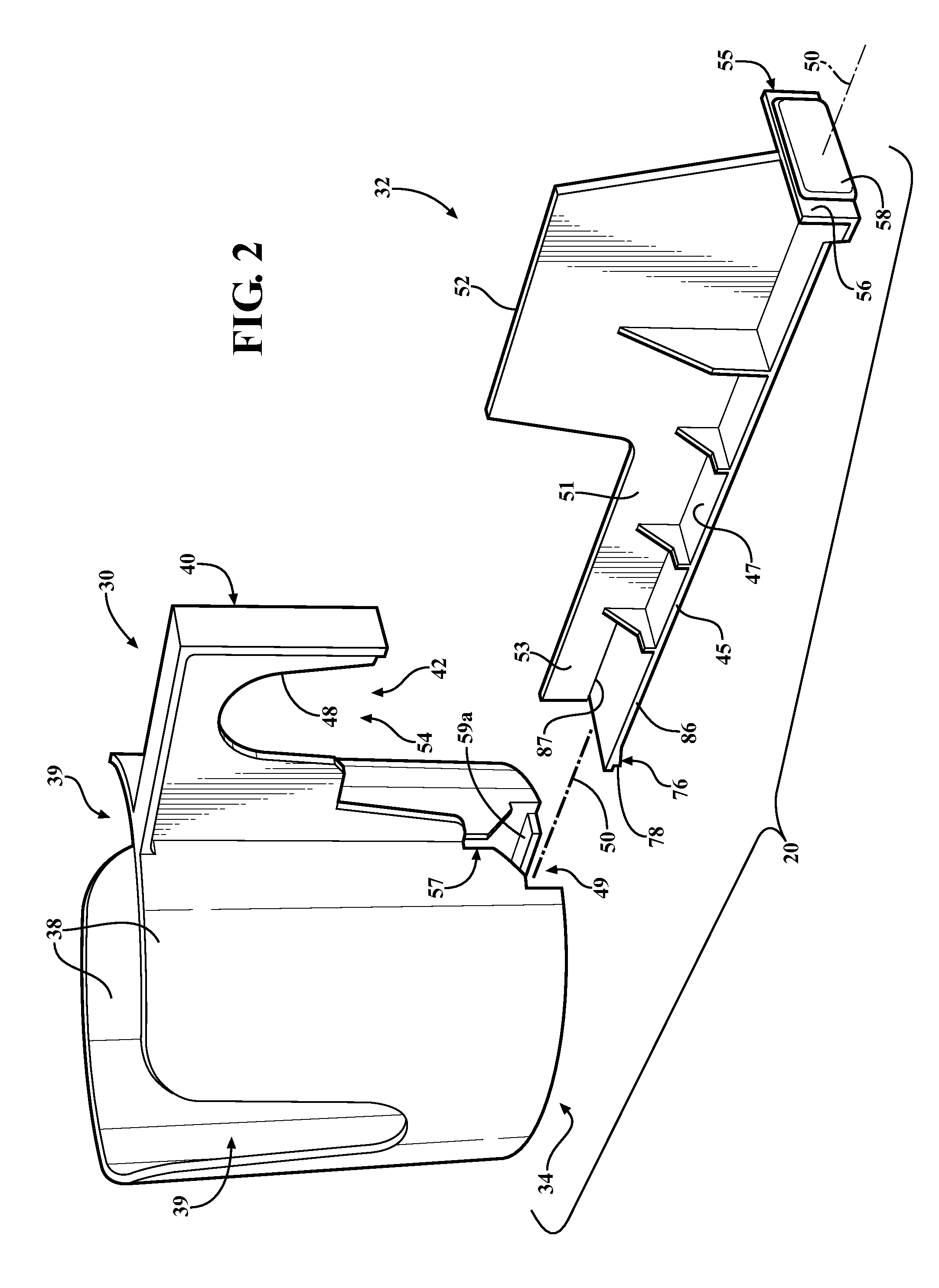
[0019]FIG. 1 shows an embodiment of a beverage container receptacle 20 that supports beverage container 22 (shown in phantom lines) and which is mounted to a fixed first structure 24, which may be the valve and piping arrangement 26 of a urinal 28. The arrangement 26 is in common use and its valve is generally known as a Flushometer-type flush valve. Arrangement 26 is also in common use on tankless, pressurized flush toilets, on which receptacle may also be utilized. Receptacle 20 may be an injection molded plastic design of two interengaged parts, including a container-holding first part 30 and a receptacle-retaining second part 32 which slidably cooperate.

[0020]The first part 30 includes integrally-formed portions that define a container holder 34 and a structure hook 40. As best shown in FIGS. 3 and 4, the container holder 34 includes a generally circular beverage container rest 36 defined by the coplanar upper edges of a plurality of spaced, integrally-formed, horizontally exten...


PUM

PropertyMeasurementUnit
relative sliding movementaaaaaaaaaa
angular movementaaaaaaaaaa
movementaaaaaaaaaa

Abstract

A beverage container receptacle adapted for installation relative to fixed first and second structures. The receptacle includes a container-holding first part having a container rest and a periphery that defines a void in which is received a portion of the fixed first structure that extends along a first axis. The periphery at least partially surrounds the first axis, and the receptacle is supported by the first structure when it is installed relative thereto. The receptacle also includes a receptacle-retaining second part slidably positioned relative to the first part. The second part is adapted for movement relative to the first structure received in the void and toward engagement with the second structure. The receptacle is adapted for being supported against angular movement in at least one direction about the first axis through the engagement of the second part with the second structure. Also, a method for installing a beverage container receptacle including the steps of: receiving a portion of a fixed first structure having a first axis in a void defined in a first part of the receptacle and at least partially surrounding the first axis with a periphery of the void; supporting the receptacle through the first structure; slidably moving a second part of the receptacle relative to the first part toward engagement with a fixed second structure; and supporting the receptacle against rotation in at least one direction about the first axis through engagement between the second part and the second structure.

Description

BACKGROUND OF THE INVENTION[0001]1. Field of the Invention[0002]The present invention relates to a receptacle for holding an individual serving beverage container, such as a cup, can, bottle, etc., and more particularly to such a receptacle adapted for being mounted to a structure such as, for example, the exposed Flushometer-type flush valve and piping arrangement of a urinal or a tankless, pressurized flush toilet.[0003]2. Description of the Related Art[0004]It is known to mount a beverage container receptacle on the Flushometer-type flush valve and piping arrangement of a urinal. Typically, prior such receptacles merely clip onto the valve assembly or related pipes, and lack a desired level of sturdiness, which results in their supporting the beverage container in an inadequately stable manner. Additionally, prior such receptacles are typically limited to being mounted at only a single position or to only one particular component of the valve and piping arrangement. It is desirab...

Claims


Application Information

Patent Timeline
Patent Type & Authority Patents(United States)
IPC IPC(8): A47K1/09
CPCA47G23/0225E03D13/005E03D13/00Y10T29/49826
Inventor DOWNS, KEVIN W.
Owner THIRD HAND MARKETING
Why Eureka
Try Eureka