
Glass-ceramic plate and method for making same

a glass-ceramic and plate technology, applied in the field of glass-ceramic plate and method for making same, can solve the problems of increasing the width of the bevel, affecting the shape of the glass, and affecting the appearance of the glass,

Inactive Publication Date: 2012-07-10
EUROKERA SOC & NOM COLLECTIF
View PDF8 Cites 2 Cited by
  • Summary
  • Abstract
  • Description
  • Claims
  • Application Information

AI Technical Summary

Benefits of technology

[0006]The present invention has therefore set itself the task of providing plates with a novel appearance, particularly ones having wider bevels than existing plates without the problems mentioned above and without detrimental effects on the other desired properties of the plates.
[0012]In general, the plate according to the invention may have one or more bevels or beveled parts, particularly one or more beveled edge(s) wider than the bevels usually made on glass-ceramic plates, and in particular may have one or more bevel(s) 35 mm or more wide, for a plate thickness that generally remains less than 4.5 mm and preferably less than 4.2 mm, this being for any type of glass-ceramic plate. The width of the bevel is to be understood as meaning the actual width measured on the plate (width L measured along the slope from the top to the bottom of the bevel as illustrated later in the figures) and not the width projected onto the plane of the plate. In particular, it is advantageous to provide a very wide bevel on the side of the plate that is intended to receive the one or more means of controlling the heating elements (control knobs, temperature or time display, etc) to give the user a better appreciation of it, better access to said elements, and to improve the esthetics. As appropriate, the raised portion adjacent to the bevel may also form a barrier protecting said control elements when products are spilt on the plate.
[0015]According to another embodiment mentioned earlier, the bevel following (on from) a raised portion is, however, preferably obtained in at least two steps, the first consisting in generating a raised portion (or relief) on the plate, for example by rolling (using an appropriate machined roller exhibiting the hollow impression of the raised portion, the dimensions of the impression generally being of the order of or slightly greater than the dimensions of the raised portion as mentioned earlier, this rolling also coinciding for example with the rolling to shape), and the second consisting in performing the beveling, by shaping (for example by polishing, using inclined grinding wheels, etc) from said raised portion. This embodiment is particularly advantageous; the bevel obtained in particular has a particularly flat and smooth surface finish (a bevel obtained directly by rolling according to the previous method could for its part have a less smooth appearance or a profile slightly hollowed or rounded at certain points).

Problems solved by technology

Each alternative form is the result of significant study and numerous tests given that it is very tricky to modify these plates (for example their composition) and / or the method of obtaining them (changing the temperature for example) without risking an unfavorable effect on the desired properties (solid structure, resistance to thermal shock, smooth appearance, high transmission in the wavelengths in the infrared domain and low transmission in wavelengths in the visible domain without in any way concealing the heating elements when they are on for safety reasons, etc).
Thus, it is known practice for the edge of the plates to be beveled using grinding techniques to give a better appearance and to allow more ergonomic operation and ease of cleaning, without detracting from the mechanical strength of the plates, as long as the bevels remain of limited width (well below 35 mm, these bevels generally being of the order of 12 mm wide), increasing the width of the bevels hitherto posing problems, particularly irregularity of the line along the crest of the bevels.

Method used


Image

  • Glass-ceramic plate and method for making same
  • Glass-ceramic plate and method for making same

Examples


Embodiment Construction

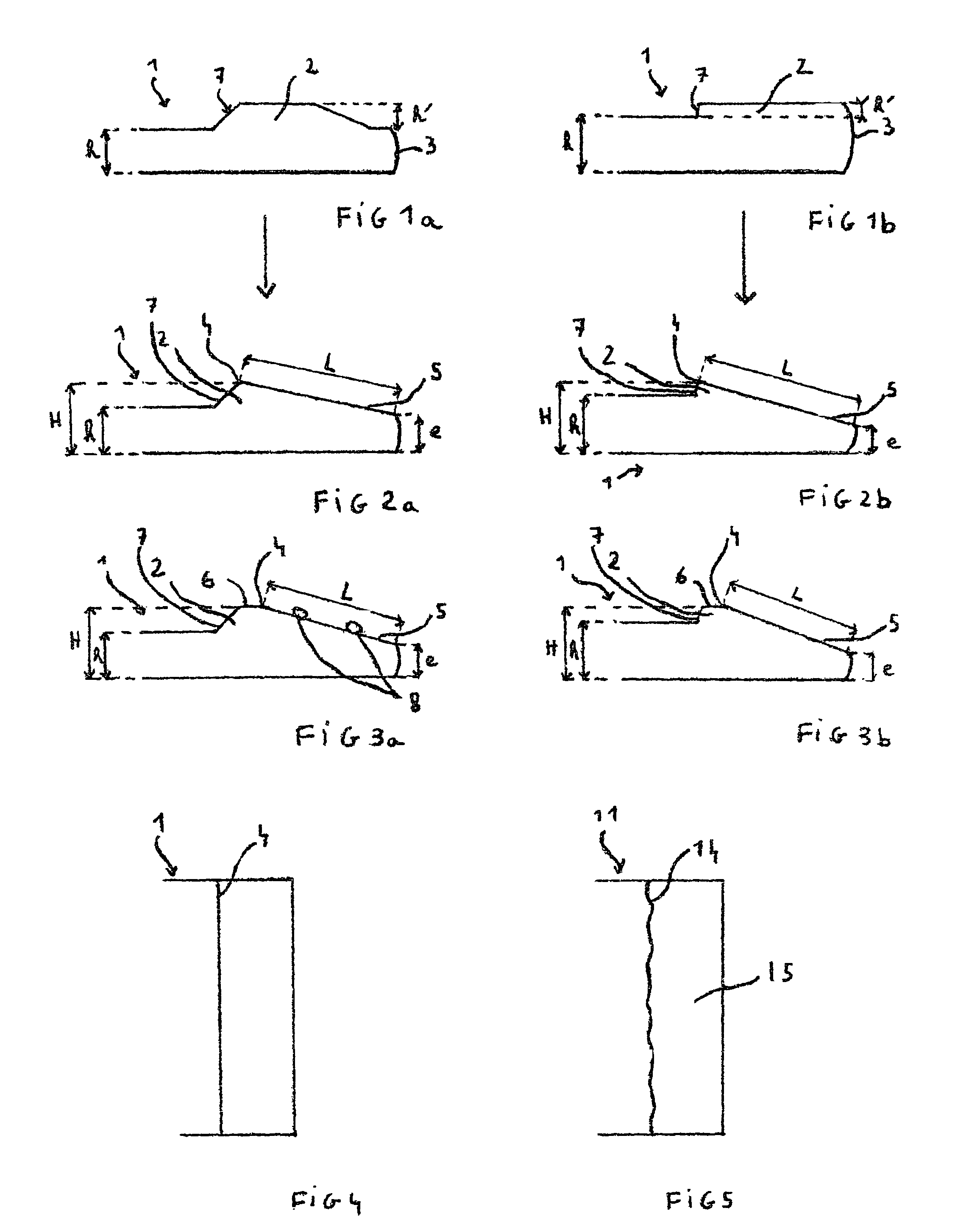
[0028]For purposes of clarity, the various parts are not necessarily drawn to scale. The same references are used for similar parts.

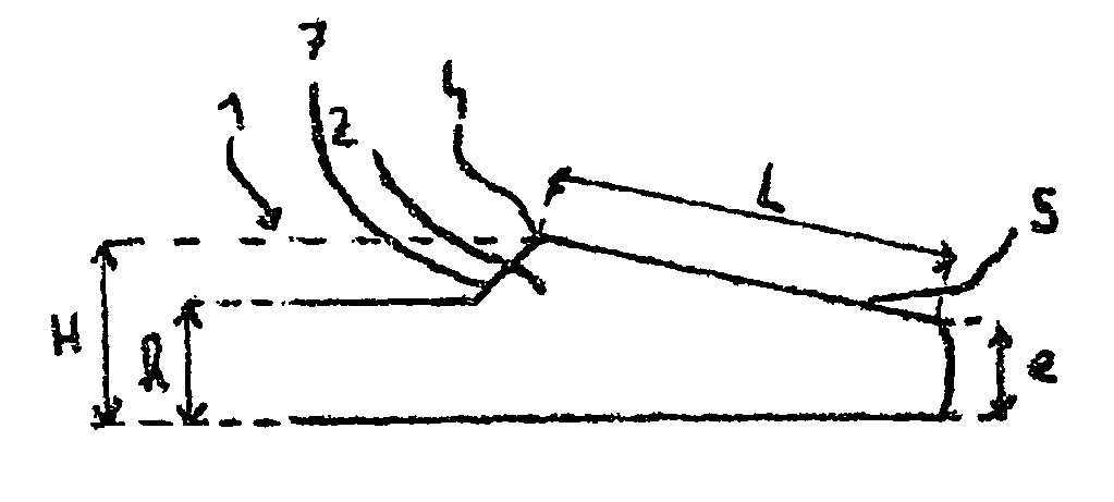
[0029]In these embodiments, the glass having for example a composition such as one of those indicated in the examples in patents FR2 657 079 or FR 2 766 816 is melted at around 1650° C. in a quantity such that a strip of glass can be rolled, from which strip plates 1 with finished sizes of the order of 55 cm×60 cm, and having a standard thickness h of 4 mm are cut.

[0030]The top roll used for rolling has a hollow impression of a depth for example of the order of or slightly greater than 2 mm and of a profile corresponding approximately to the profile of the additional thickness that is to be generated, the bottom roll for its part being engraved to form pegs (not depicted) on the underside of the plate. In the case of FIG. 1a, the additional thickness 2 is generated on the plate a few millimeters away from the cut region (and therefore from the edge of t...


PUM

PropertyMeasurementUnit
Lengthaaaaaaaaaa
Thicknessaaaaaaaaaa
Thicknessaaaaaaaaaa

Abstract

A glass-ceramic plate intended in particular to cover heating elements, and having at least one bevel 35 mm or more wide, a method of manufacturing the plate, and a cooking appliance including the plate.

Description

[0001]The present invention relates to a glass-ceramic plate intended in particular to cover heating elements, particularly intended to act as a hot plate, the underlying heating elements associated with this plate being, for example, halogen or radiant or induction hot plate elements.BACKGROUND OF THE INVENTION[0002]Sales of glass-ceramic hot plates have been increasing constantly for several years. This success is particularly explained by the attractive appearance of these plates and by their ease of cleaning.[0003]Let us remember that a glass-ceramic originates from a glass, known as a precursor glass, the specific chemical composition of which allows by suitable heat treatment known as ceramification (or ceramization) to bring about controlled crystallization. This partially-crystallized specific structure gives the glass-ceramic unique properties.[0004]There are currently different types of glass-ceramic plates the appearance of which can vary according to the type of heating ...

Claims


Application Information

Patent Timeline
IPC IPC(8): B32B3/00B32B23/02F24C15/10F24C3/00C03B13/08C03B23/02H05B3/74
CPCC03B13/08C03B23/02H05B3/74H05B3/748Y10T428/24777Y10T428/219Y10T428/24479
Inventor HOBON, CAROLRENAULT, ALAINHARMAND, HELENEVILATO, PABLO
Owner EUROKERA SOC & NOM COLLECTIF
Learn More