Electrical switchgear cabinet

a switchgear cabinet and switchgear technology, applied in the direction of electrical apparatus casings/cabinets/drawers, machine supports, coupling device connections, etc., can solve the problems of unfavorable transportation and inability to dismantle, and achieve the effect of convenient assembly

Inactive Publication Date: 2012-07-10
ABB (SCHWEIZ) AG
View PDF6 Cites 3 Cited by
  • Summary
  • Abstract
  • Description
  • Claims
  • Application Information

AI Technical Summary

Benefits of technology

[0005]An aspect of the present invention is to provide an electrical switchgear cabinet of the type mentioned in the introduction which can be dismantled for transportation purposes and furthermore can be easily assembled.
[0010]The angle of approximately 45° or perhaps also exactly 45° has the advantage of optimum production options.

Problems solved by technology

The disadvantage of this structural solution is that the switchgear cabinet itself cannot be dismantled but has to be produced in the factory, this being unfavorable in terms of transportation.

Method used


Image

  • Electrical switchgear cabinet
  • Electrical switchgear cabinet
  • Electrical switchgear cabinet

Examples


Embodiment Construction

[0036]Reference will now be made to FIG. 1.

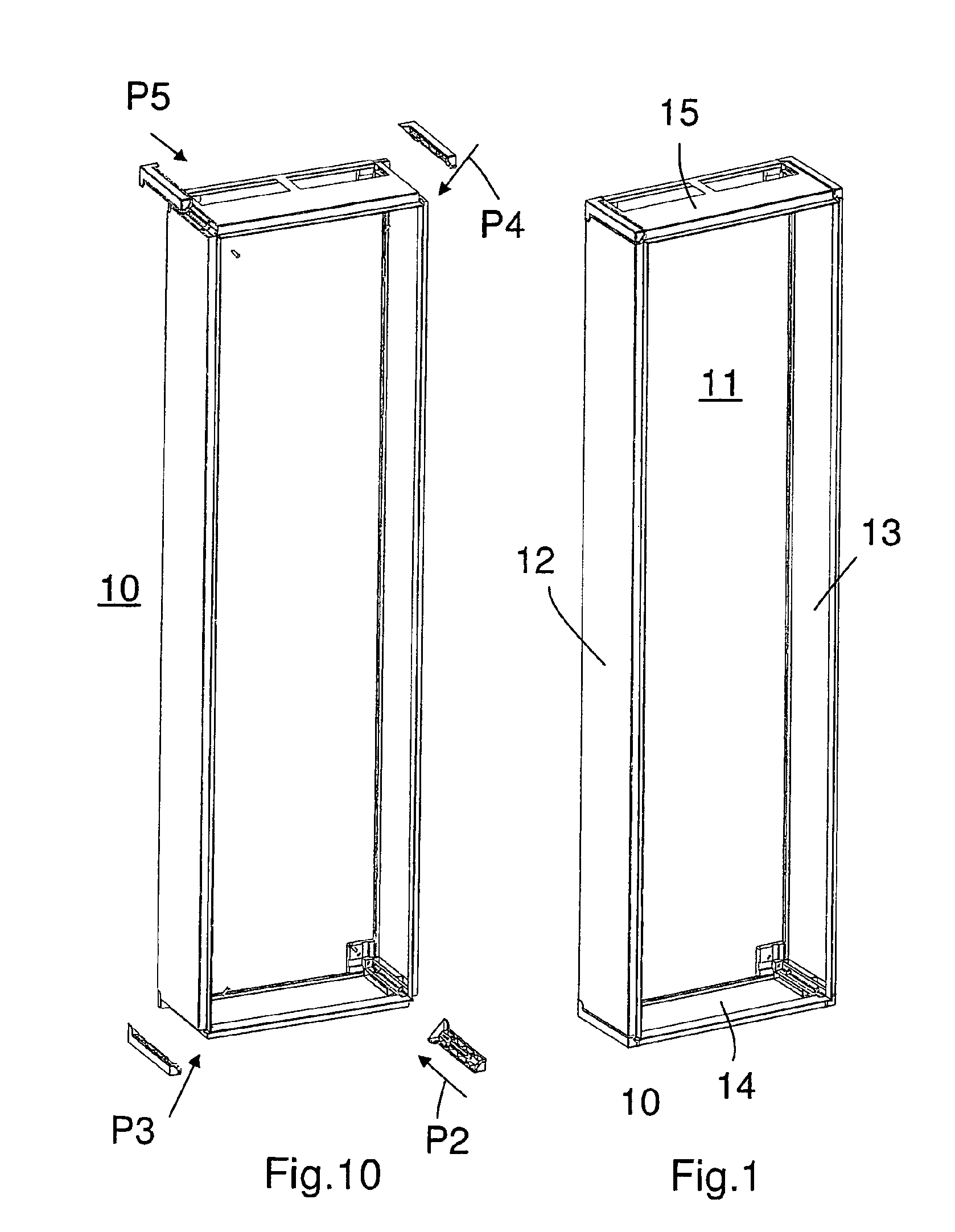
[0037]FIG. 1 shows an internal view of a switchgear cabinet 10 which has a rear wall 11, two side walls 12 and 13, a base wall 14 and a ceiling wall 15. Internal components and the front door are not shown.

[0038]Reference will now be made to FIG. 2

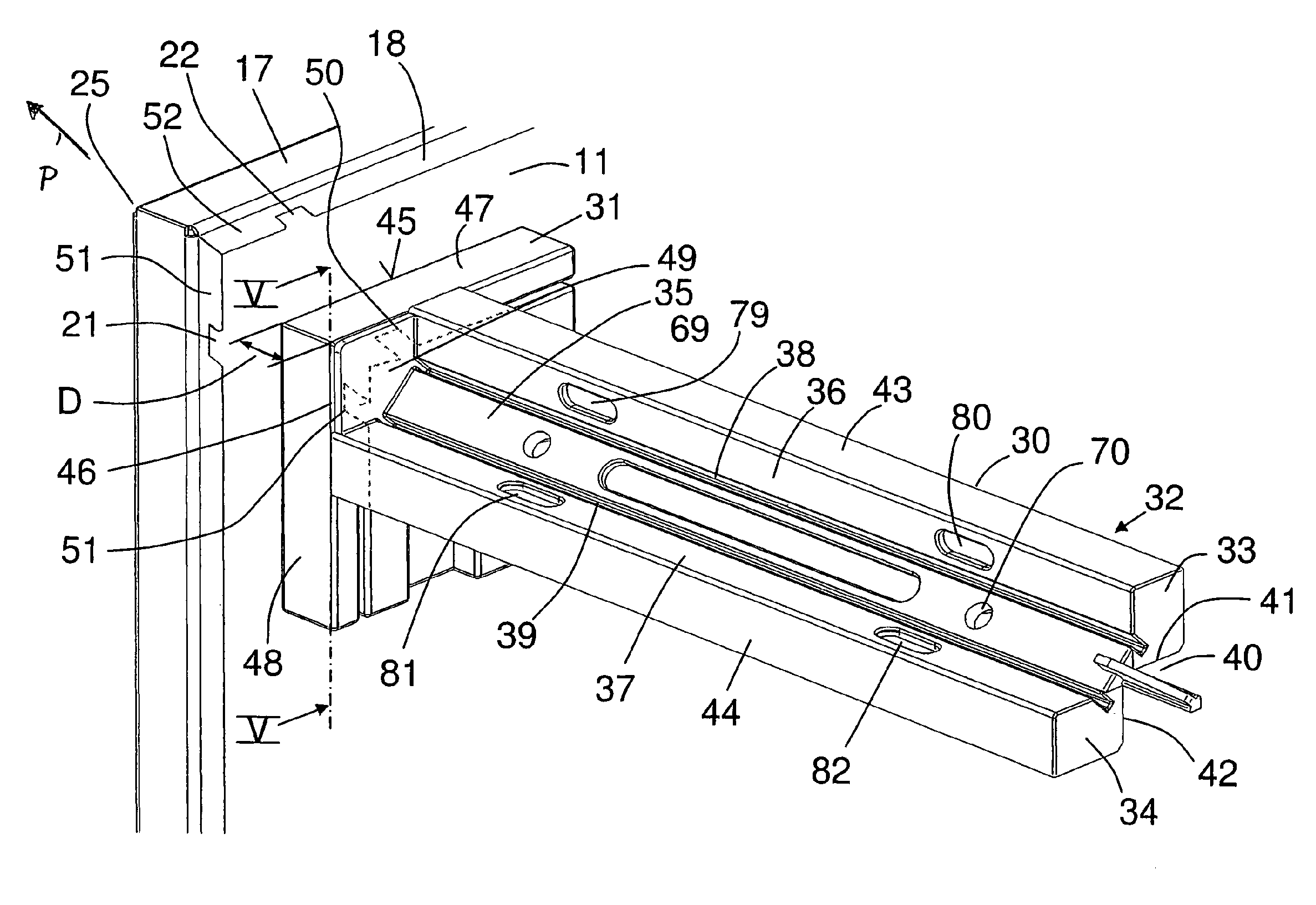
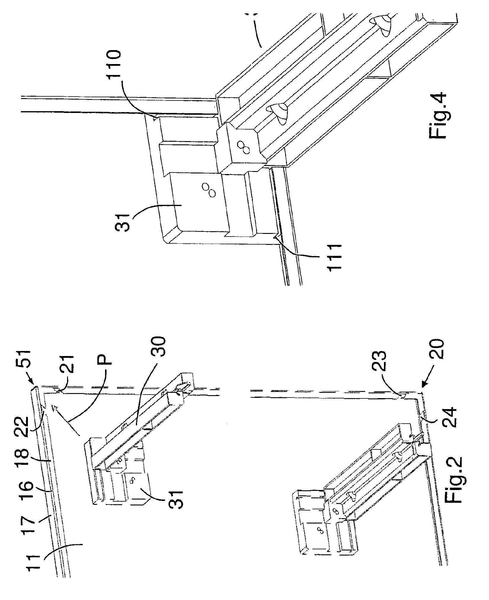
[0039]FIG. 2 shows a perspective view of the right-hand region of the inner side of the rear wall 11 which has peripheral, inwardly projecting bent edges 16 which have a bar 17 which runs at right angles to the rear wall and a limb 18 which runs at right angles to said bar, with the limb 18 running parallel to the inner face of the rear wall 11.

[0040]In the region of the corners, of which only the top right-hand corner 19 and the bottom right-hand corner 20 are illustrated, obliquely running cutouts 21, 22 or 23 and 24, also called slots, are located in the limbs 18, said cutouts forming an angle of 45° in relation to the adjacent vertical or horizontal side edge of the rear wall 11, with the open...


PUM


Abstract

An electrical switchgear cabinet for an electrical service distribution panel includes a rear wall having four corners and four side edges and a peripheral L-shaped first bent edge disposed on each of the four side edges; a first side wall with at least two bent edges; a base wall with at least two bent edges; and a first attachment part disposed at a first corner of the rear wall and insertable behind the first bent edges of two of the four side edges, wherein the first attachment part has two longitudinally running slots, a first slot receiving one of the at least two first side wall bent edges and a second slot receiving one of the at least two base wall bent edges.

Description

[0001]This is a U.S. National Phase Application under 35 U.S.C. §171 of International Application No. PCT / EP2008 / 005963 filed on Jul. 21, 2008, which claims priority to German Application No. DE 10 2007 034 513.7, filed on Jul. 24, 2007. The International Application was published in German on Jan. 29, 2009 as WO 2009 / 012962 under PCT[0002]The invention relates to an electrical switchgear cabinet for an electrical service distribution panel.BACKGROUND[0003]Switchgear cabinets for electrical service distribution panels of this type have a rear wall, two side walls, a base wall and a ceiling wall, and these walls are welded to one another at their edges. A door is fitted in an articulated manner to one of the vertical free edges of the switchgear cabinet which faces forward and the interior of the switchgear cabinet is accessible or can be closed by said door.[0004]The disadvantage of this structural solution is that the switchgear cabinet itself cannot be dismantled but has to be pro...

Claims


Application Information

Patent Timeline
Patent Type & Authority Patents(United States)
IPC IPC(8): H05K5/00
CPCH02B1/30H02B1/014Y10S248/906
Inventor ROTH, MICHAEL
Owner ABB (SCHWEIZ) AG
Why Eureka
Try Eureka