

Magnetic resonance imaging system and magnetic resonance imaging method
a magnetic resonance imaging and magnetic resonance imaging technology, applied in the field of magnetic resonance imaging system and magnetic resonance imaging method, can solve the problem of difficult to image fine blood vessels with high precision, and achieve the effects of high temporal resolution, high contrast, and high precision
- Summary
- Abstract
- Description
- Claims
- Application Information
AI Technical Summary
Benefits of technology
Problems solved by technology
Method used
Image

Examples
first modified example
[0066]In the first acquisition pattern and the second acquisition pattern, the sizes of the acquisition areas may be changed instead of changing the data acquisition order of the acquisition areas.
[0067]FIG. 7 is a diagram illustrating an example where the first acquisition pattern and the second acquisition pattern are different from each other in the sizes of their acquisition areas. FIG. 8 is a diagram illustrating an example of a pulse sequence in the second acquisition pattern according to a first modified example.
[0068]The acquisition areas in the first acquisition pattern are the same as the above-mentioned embodiment and the pulse sequence shown in FIG. 5 is applied without any change. On the contrary, in the second acquisition pattern, acquisition area A is enlarged and acquisition area D is reduced. The amounts of data of acquisition area B and acquisition area C are not changed in the first acquisition pattern and the second acquisition pattern, but the positions thereof ...
second modified example
[0070]The speed-up rate, that is, the number of acquisition areas, may be changed in the first acquisition pattern and the second acquisition pattern.
[0071]FIG. 9 is a diagram illustrating an example where the first acquisition pattern and the second acquisition pattern are different from each other in the number of acquisition areas. FIG. 10 is a diagram illustrating an example of a pulse sequence in the second acquisition pattern according to a second modified example.
[0072]The speed-up rate in the first acquisition pattern the same as the above-mentioned embodiment and the pulse sequence shown in FIG. 5 is applied without any change. On the contrary, in the second acquisition pattern, the speed-up rate which is 2 in the first acquisition pattern is lowered to 1.5. That is, the number of the acquisition area which was 4 in the first acquisition pattern is changed to 3. Further, acquisition area A, acquisition area B, and acquisition area C in the second acquisition pattern are set...
third modified example
[0075]The change of the acquisition pattern may be made in synchronization with the time point when a user instructs a change in the pattern.
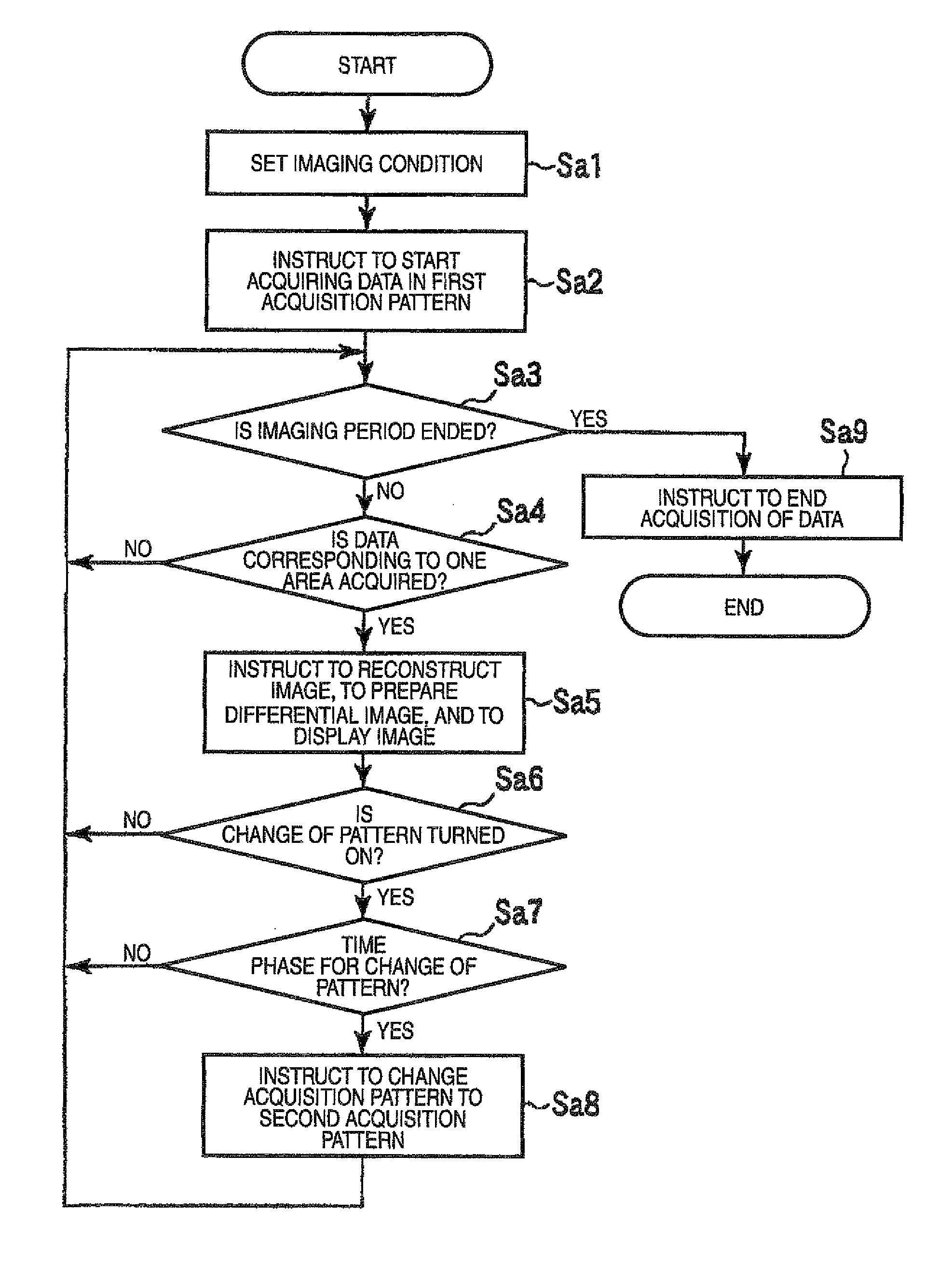
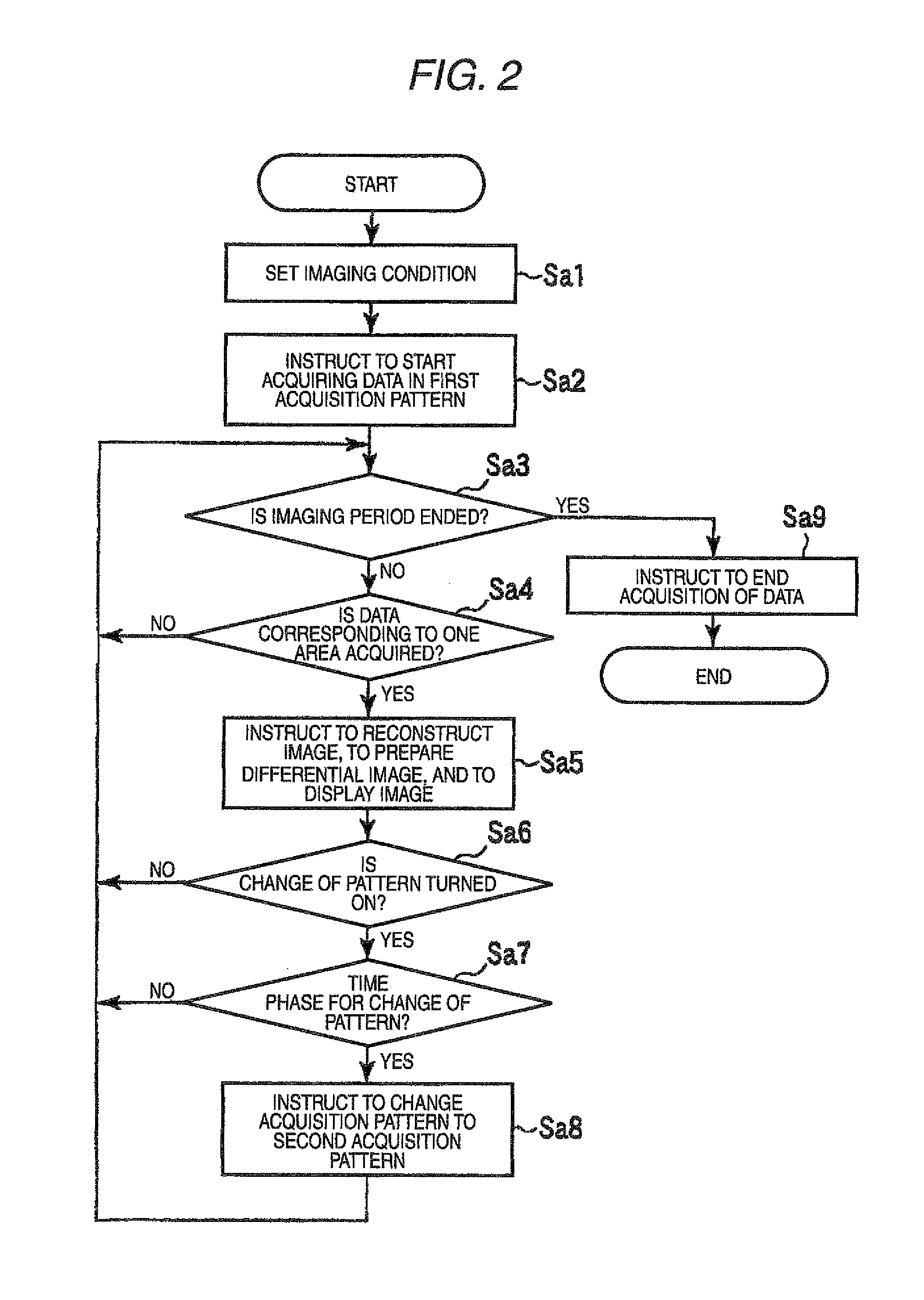
[0076]FIG. 11 is a flowchart illustrating a flow of processes performed by the host computer 16 according to a third modified example. The same processes as shown in FIG. 2 are referenced by the same reference signs and a detailed description thereof is omitted. In the following, only operations which are not the same as the above-mentioned embodiment will be described.
[0077]The host computer 16 performs the process of step Sb1 instead of step Sa1. In step Sb1, the host computer 16 sets an imaging condition, but does not set the ON / OFF of the change in an acquisition pattern and the time phase to change the acquisition pattern.
[0078]The host computer 16 additionally waits for the pattern change instruction in step Sa2, when waiting in steps Sa3 and Sa4. In response to the pattern change instruction, the host computer 16 performs the process of ...
PUM
 Abstract
Description
Claims
Application Information