Brake light switch for engine brake systems

Inactive Publication Date: 2012-07-10
KIRKMAN ROBERT
2 Cites 5 Cited by

AI-Extracted Technical Summary

Problems solved by technology

Moreover, the circuits for the engine brake side do not ...

Method used

[0012]FIG. 1 shows the circuit of the instant invention. It includes an engine brake operating system that includes three brake solenoids 105. These solenoids are used to activate the engine brakes. Typically, they are operated through switches (not shown) mounted in the truck cab. When the switches are thrown, positive power is sent to the solenoids positive terminals to engage the solenoids. In most cases, large trucks employ three solenoids that can be engaged in stages: from one to three solenoids in three steps. The addition of more solenoids increases the braking force applied. Unlike the prior art designs, which take power from the solenoid switches directly, the instant design takes positive power from each of the three soleno...

Abstract

Brake light circuits for use with engine brakes for both positive switch and negative switch brake light circuits. The brake light circuits for the engine brakes do not function until the engine brake solenoids are energized. This ensures that only true brake indications are indicated. In the case of the positive switch, the circuit uses a relay in parallel with the existing brake light switch to active the brake lights whenever the engine brake solenoids are energized. In the case of the negative switch circuit, the original brake pedal switch is connected to ground. It is used to operate a brake light relay that sends positive power to the brake lights. A second relay is used to close the ground connection to activate the original engine brake relay. In both cases, diodes are used to prevent back feed through the bake solenoids or other components.

Application Domain

Optical signallingBraking components +1

Technology Topic

Brake lightPositive power +6

Image

  • Brake light switch for engine brake systems
  • Brake light switch for engine brake systems
  • Brake light switch for engine brake systems

Examples

  • Experimental program(1)

Example

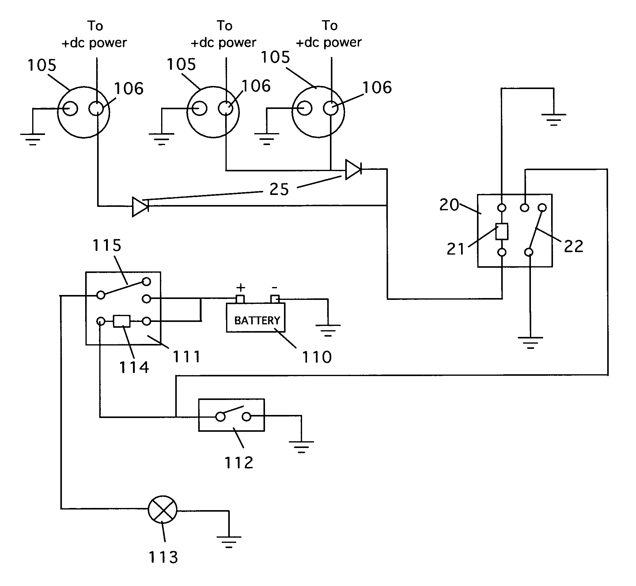
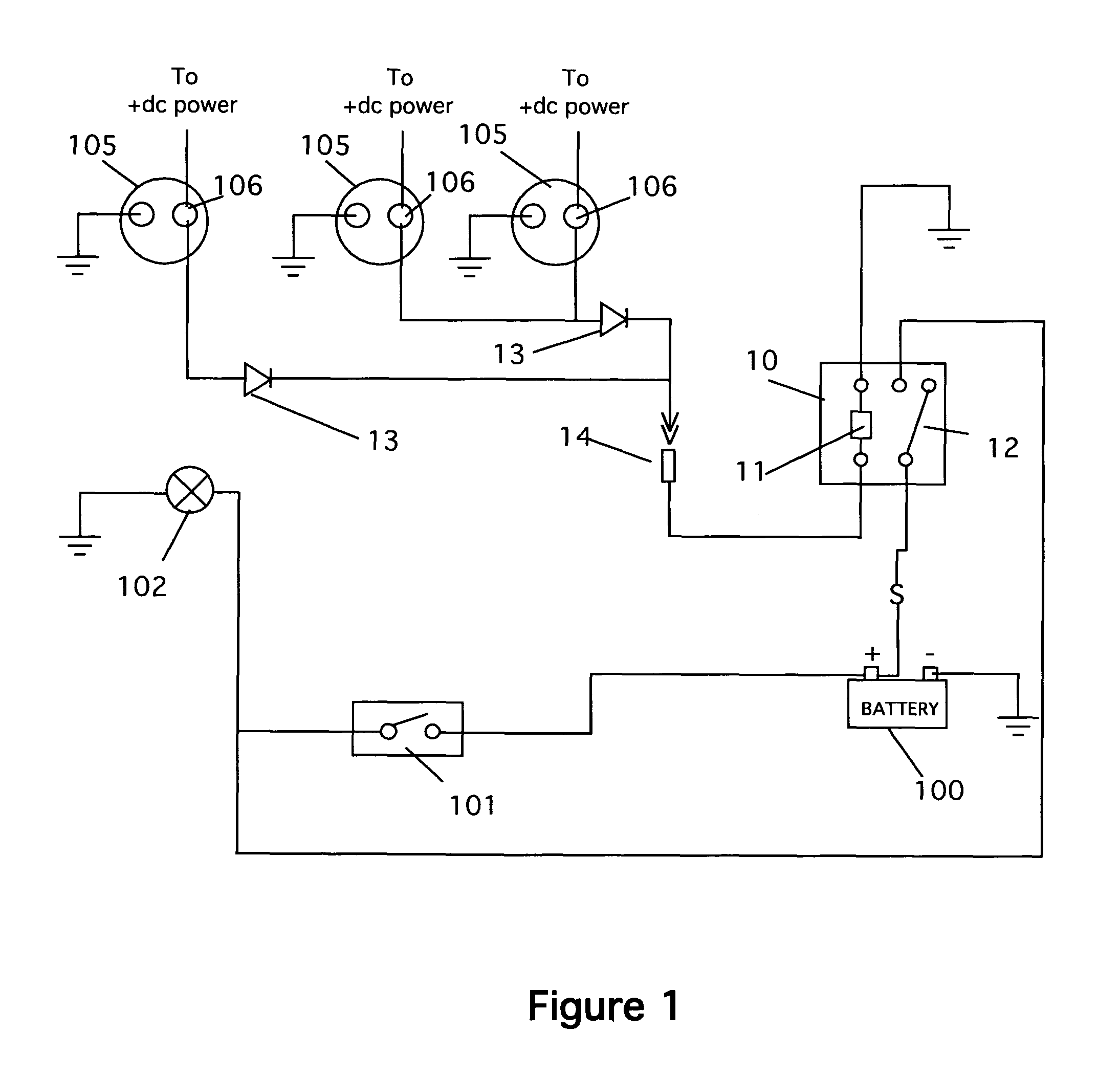
[0011]Referring now to FIG. 1, the basic positive switch system contains a power source 100, which is typical one of the vehicle batteries or main engine power source, a brake switch 101, which is typically attached to the brake pedal, and the set of brake lights 102. Under ordinary circumstances, when the driver engages the brakes by pressing on the foot pedal, switch 101 causes the brake lights 102 to illuminate. FIG. 1 shows the additional circuits used to illuminate the brake lights when the engine brakes are engaged.
[0012]FIG. 1 shows the circuit of the instant invention. It includes an engine brake operating system that includes three brake solenoids 105. These solenoids are used to activate the engine brakes. Typically, they are operated through switches (not shown) mounted in the truck cab. When the switches are thrown, positive power is sent to the solenoids positive terminals to engage the solenoids. In most cases, large trucks employ three solenoids that can be engaged in stages: from one to three solenoids in three steps. The addition of more solenoids increases the braking force applied. Unlike the prior art designs, which take power from the solenoid switches directly, the instant design takes positive power from each of the three solenoid terminals. This ensures that the brake lights are only illuminated when the braking is actually being applied.
[0013]To operate the system a relay 10 is used to control the operation of the lights when the engine brake is applied. The relay 10 has a coil 11 and a single throw contact 12 that is operated by the coil. Positive power is taken from the solenoid terminals 106 and is then routed through diodes 13 through a wiring harness and connectors 14. A wire I routed to one side of the coil 11 as shown (the other side of the coil goes to ground). When any of the engine brake solenoids receive positive power, the coil 11 becomes energized, which causes the contact 12 to trip. When that happens, positive power, which is connected to one side of the contact, as shown, is routed directly to the brake light system.
[0014]Many trucks also use a “negative switch” system to operate the brake lights. In this system, positive power is routed to the brake lights through a relay. FIG. 2 shows this circuit. The system consists of a power source 110, a relay 111, a brake pedal switch 112 and the brake lights 113. In this system, when the driver engages the brake pedal, a ground circuit is closed between the chassis ground and one side of the relay coil 114. Positive power is routed to the other side of the coil. Thus, when the brake pedal is depressed, the relay coil is energized and the single pole contact 115 trips, which puts positive power to the brake light system.
[0015]In the instant invention, this circuit is modified. FIG. 2 shows the solenoid coils 105 as before, a second relay 20 is used to control the brake lights. In this circuit, positive power is routed to the relay coil 21 from the positive terminals 106 of the solenoids, a gain using diodes 25 to prevent unwanted back flow of power. Thus, when the solenoids are energized, the relay coil 21 is energized and the relay contact 22 trips. In this case, the contact 22 places chassis ground on the open side of the coil in relay 111. In this way, the relay coil is energized and the relay contact 115 energizes the brake lights 113.
[0016]The present disclosure should not be construed in any limited sense other than that limited by the scope of the claims having regard to the teachings herein and the prior art being apparent with the preferred form of the invention disclosed herein and which reveals details of structure of a preferred form necessary for a better understanding of the invention and may be subject to change by skilled persons within the scope of the invention without departing from the concept thereof.

PUM

no PUM

Description & Claims & Application Information

We can also present the details of the Description, Claims and Application information to help users get a comprehensive understanding of the technical details of the patent, such as background art, summary of invention, brief description of drawings, description of embodiments, and other original content. On the other hand, users can also determine the specific scope of protection of the technology through the list of claims; as well as understand the changes in the life cycle of the technology with the presentation of the patent timeline. Login to view more.
Why Eureka
Try Eureka