
Magnetized mounting bracket

a mounting bracket and magnet technology, applied in the field of magnetized mounting brackets, can solve the problems of equipment tearing at the clamping location, damage to the bracket, and hydraulic hose ripping, so as to avoid fire hazards, prevent hydraulic hose ripping, and quick and efficient reconnection

Inactive Publication Date: 2005-08-04
MCLELLAN ROBIN S
View PDF22 Cites 40 Cited by
  • Summary
  • Abstract
  • Description
  • Claims
  • Application Information

AI Technical Summary

Benefits of technology

[0007] (c) a friction layer below the magnetic base to separate the magnetic base from direct contact with the ferromagnetic surface whereby the magnetic base acts to releasably retain the support portion on the ferromagnetic surface and the friction layer acts to prevent slippage.
[0012] The use of magnets to anchor the mounting bracket of the present invention to a surface avoids the disadvantages of alternative mounting schemes such as threaded fasteners or welding. The magnets allow for a breakaway connection between the mounting bracket and the anchor surface. For example, when used with heavy machines to retain conduits, in the event that the hoses or the bracket catch on debris, if the dislodging force exceeds the magnetic clamping force, the mounting bracket of the present invention will breakaway from the anchor surface to prevent ripping of the hydraulic hoses. The magnets allow for quick and efficient reconnection to the anchor surface. Re-positioning of the mounting bracket is also readily accomplished by prying up the bracket using a force greater than the magnetic force. The magnets eliminate welding thereby avoiding the fire hazard associated with welding activities in the field. Installation time for the mounting bracket is virtually eliminated.

Problems solved by technology

Because the mounting brackets are fixed in place, there is the possibility that hydraulic hoses that snag or catch on debris during operation of the heavy equipment will tear at the clamping location.
Rigidly fixed mounting brackets are also subject to collision with objects during operation of the machine which may damage the bracket and make disassembly difficult.
If a mounting bracket does break off from its anchoring location, re-welding is often required to complete repairs.

Method used


Image

  • Magnetized mounting bracket
  • Magnetized mounting bracket
  • Magnetized mounting bracket

Examples


Embodiment Construction

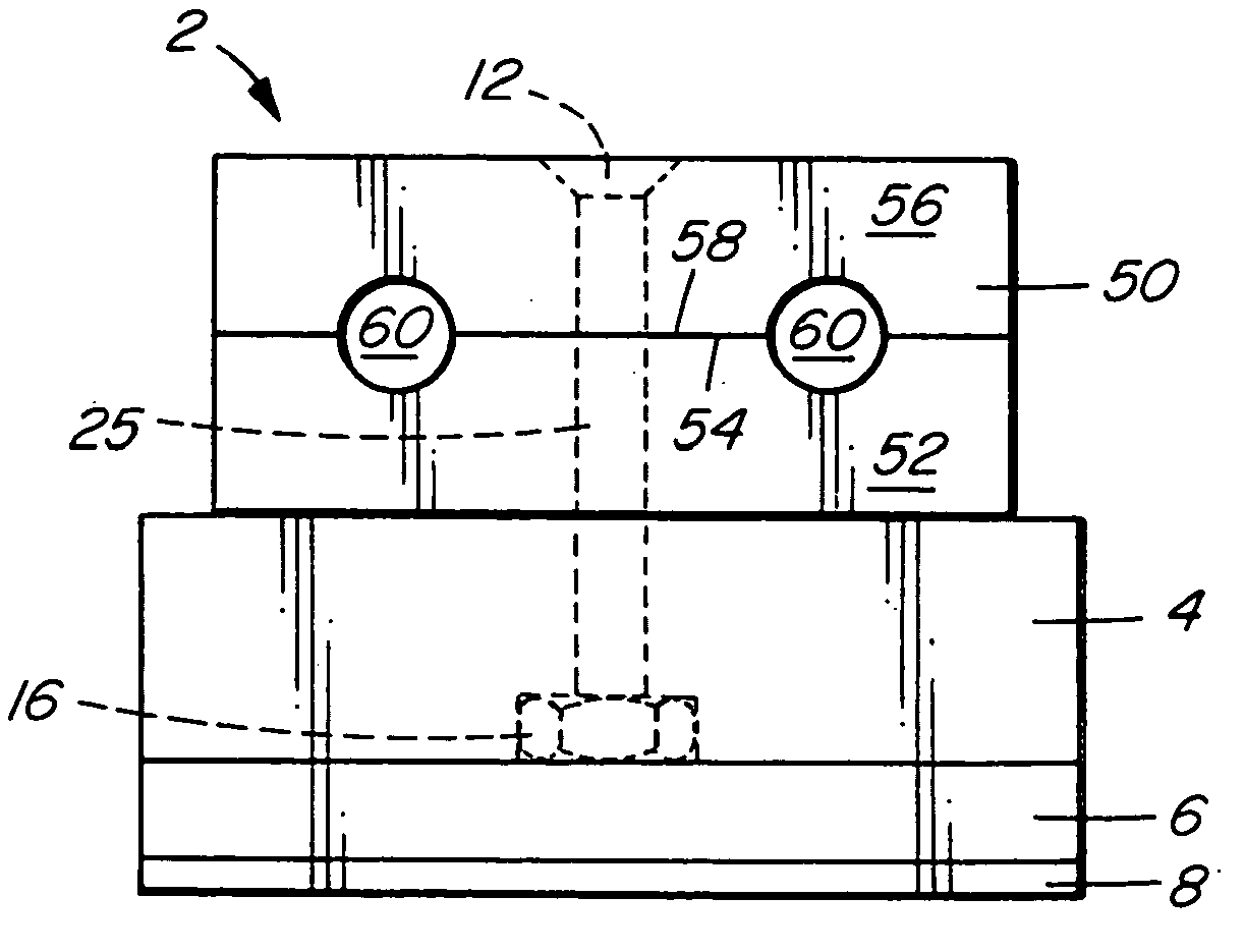
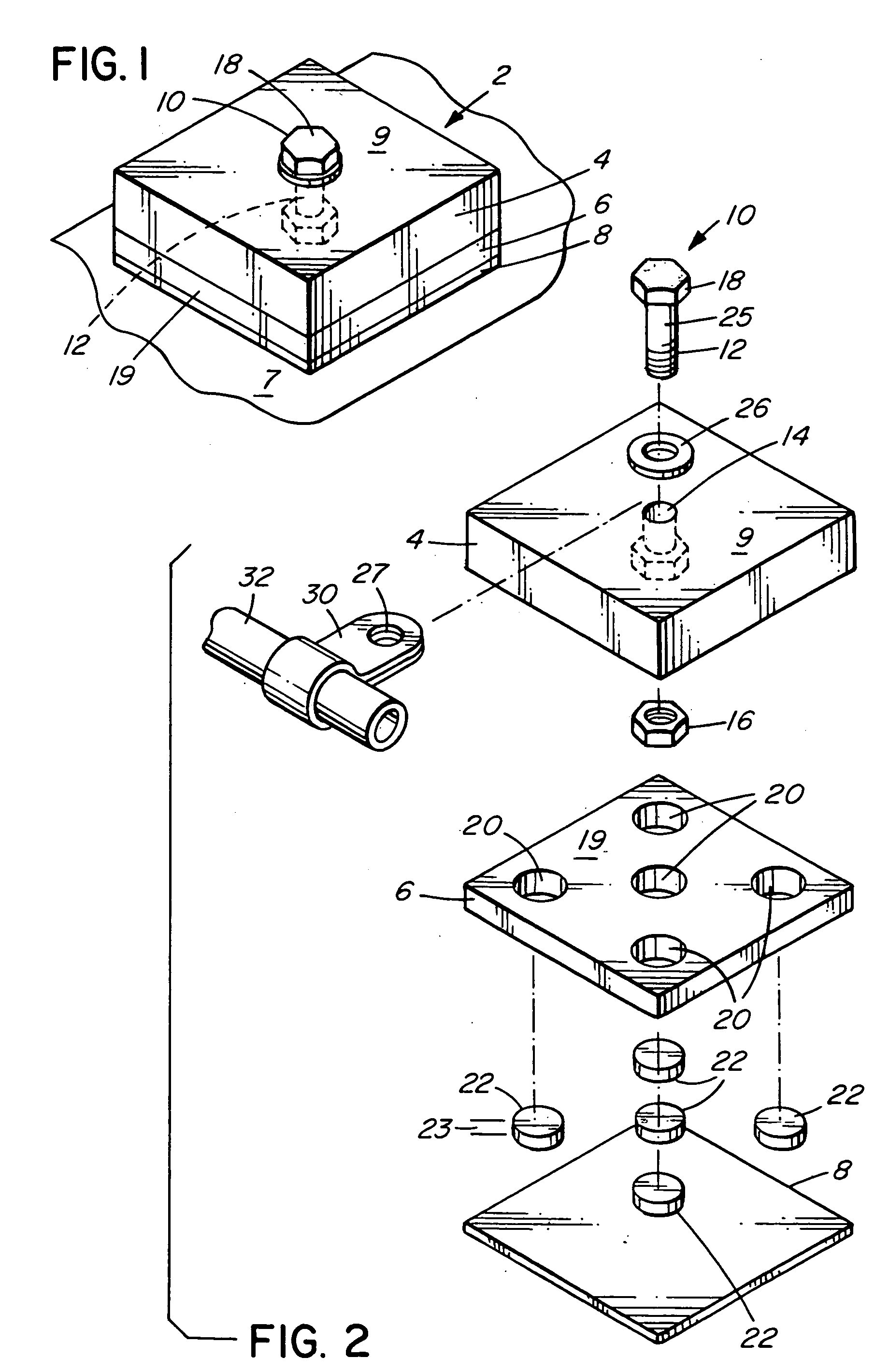
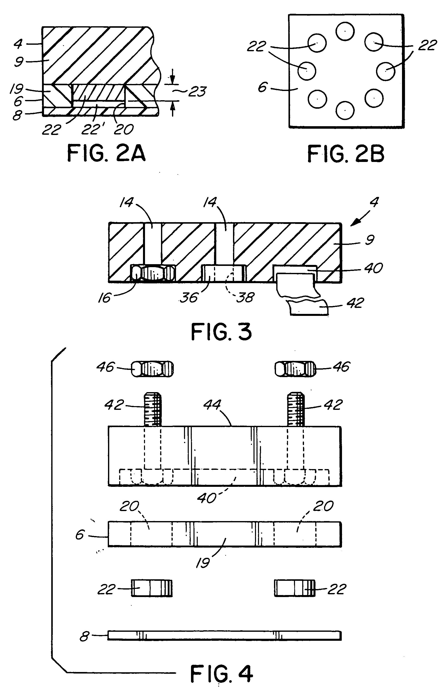
[0032] Referring to FIGS. 1 and 2, there is shown a first preferred embodiment of the mounting bracket apparatus 2 of the present invention suitable for mounting an object to a ferromagnetic surface. Mounting bracket 2 comprises an upper support portion 4 adapted to retain the object to be anchored. Below upper support portion 4, a lower magnetic base 6 is provided to connect to a ferromagnetic surface 7. Interposed between magnetic base 6 and the ferromagnetic surface 7 is a friction layer 8 to separate the magnetic base from direct contact with the ferromagnetic surface. Magnetic base 6 acts to releasably retain upper support portion 4 on the ferromagnetic surface while friction layer 8 acts to minimize slippage of the entire assembly.

[0033] In the preferred arrangement of FIGS. 1 and 2, upper support portion 4 is preferably formed from a block 9 of elastomeric material such as synthetic rubber, also known as neoprene, of sufficient hardness to maintain its shape. Other suitable ...


PUM


Abstract

An apparatus for mounting an object to a ferromagnetic surface comprising an upper support portion adapted to retain the object with a lower magnetic base to the support portion that is attractable to the ferromagnetic surface. A friction layer below the magnetic base separates the magnetic base from direct contact with the ferromagnetic surface whereby the magnetic base acts to releasably retain the support portion on the ferromagnetic surface and the friction layer acts to prevent slippage and provides cushioning. The mounting bracket is particularly suited to anchoring hoses, lines or cables to heavy equipment. The mounting bracket also useful for mounting equipment such as fire extinguishers or other safety equipment to a mounting location in a vehicle. Vehicle emergency lights or brake lights attached to the mounting bracket are readily installable on the exterior of a vehicle at any desired location and removable without damaging the vehicle finish.

Description

FIELD OF THE INVENTION [0001] This invention relates to a mounting bracket for holding an article in fixed relationship to a surface. In particular, the mounting bracket of the present invention relies on magnetic force to hold an article to a ferromagnetic surface. BACKGROUND OF THE INVENTION [0002] Mounting brackets for permanently or releasably securing an article to a surface are well known and find application in all types of environments. In machines of all types, mounting brackets are used to retain conduit in place to adjacent the machine or a component thereof. For example, conduits in the form of rigid lines or flexible hoses used to transport lubricants, coolants, air, hydraulic fluid or the like between different parts of the machine, are often held in position by mounting brackets. In heavy equipment, such as back hoes or the like, flexible hydraulic hoses to control grasping, cutting or digging tools, are held in position at specific locations by mounting bracket incor...

Claims


Application Information

Patent Timeline
IPC IPC(8): A47G1/17B60Q1/26F16B1/00F16B2/00F16B2/06F16L3/08F16M13/02
CPCB60Q1/2615F16B2001/0035F16B2/065F16B2/005F16B2200/83
Inventor MCLELLAN, ROBIN S.
Owner MCLELLAN ROBIN S
Learn More