Interactive display system

a display system and interactive technology, applied in the field of interactive display systems, can solve the problems of limited light pen sensing technology, limited presentation, and limited speech speaker to visual information contained within the presentation, and achieve the effect of reducing human perceptibility

Inactive Publication Date: 2012-07-10
INTERPHASE CORP
View PDF15 Cites 25 Cited by
  • Summary
  • Abstract
  • Description
  • Claims
  • Application Information

AI Technical Summary

Benefits of technology

[0019]Embodiments of this invention provide such a system and method in which positioning of the pointing device can be performed rapidly and efficiently, using human-imperceptible positioning information displayed using visible light and at the nominal frame rate of the display.
[0021]Embodiments of this invention provide such a system and method in which positioning of the location at which the pointing device is aimed is performed efficiently and rapidly.
[0031]According to another aspect of the invention, the display system generates later positioning targets at locations, sizes, and other attributes that are selected in response to the image of the positioning target captured from previous frames. Accurate and rapid determination of the pointed-to location of the display is facilitated by the pointing device capturing a portion of the displayed image in which the positioning target is prominent, and closely matches the generated positioning target. According to this aspect of the invention, the positioning target is altered to correct for distance of the pointing device from the display, rotation of the pointing device, location of the pointing device “off-axis” from the display, and other distortions between the positioning target as generated and as captured by the pointing device.

Problems solved by technology

In this type of presentation, however, the speaker is essentially limited to the visual information contained within the presentation as generated, typically as displayed in a sequential manner (i.e., from one slide to the next, in a given order).
This limitation can detract from the presentation, especially in the large audience context.
Of course, this light pen sensing technology is limited to CRT displays, because of its dependence on sensing the raster-scan timing.
These conventional pointing devices necessarily constrain the displayed image, however, requiring either a displayed cursor element or perceptible image content varying within the displayed image in order to determine the pointed-to location of the positioning device.
In some situations, the presence of a cursor may be distracting or superfluous to the viewing audience.
In addition, these devices would be precluded from use in a “white board” context, for example if the user wished to hand-write or draw an image on an otherwise-blank display field.
In addition, this approach involves a large amount of data processing and bandwidth to communicate and compare the captured image with the displayed image.
However, this approach is limited to those situations in which the user is sufficiently distant from the display that the field of view of the pointing device includes one or more display corners, and would appear not to operate well in smaller environments or in those situations in which the speaker is near a large display.
Rapid positioning of the device in this system requires a high duty cycle of navigation frames within the displayed sequence, which reduces the brightness and contrast of the displayed gaming images to the human user; conversely, less human-perceptible impact can be attained at a cost of longer positioning detection times and thus reduced game performance.
These systems are of course limited to digital micromirror-based modulator projection display systems, and typically require additional projection subsystems (including an additional modulator) to operate with reasonable performance.

Method used


Image

  • Interactive display system
  • Interactive display system
  • Interactive display system

Examples


Embodiment Construction

[0051]The present invention will be described in connection with one or more of its embodiments, namely as implemented into a computerized presentation system including a display visible by an audience, as it is contemplated that this invention will be particularly beneficial when applied to such a system. However, it is also contemplated that this invention can be useful in connection with other applications, such as in gaming systems, general input by a user into a computer system, and the like. Accordingly, it is to be understood that the following description is provided by way of example only, and is not intended to limit the true scope of this invention as claimed.

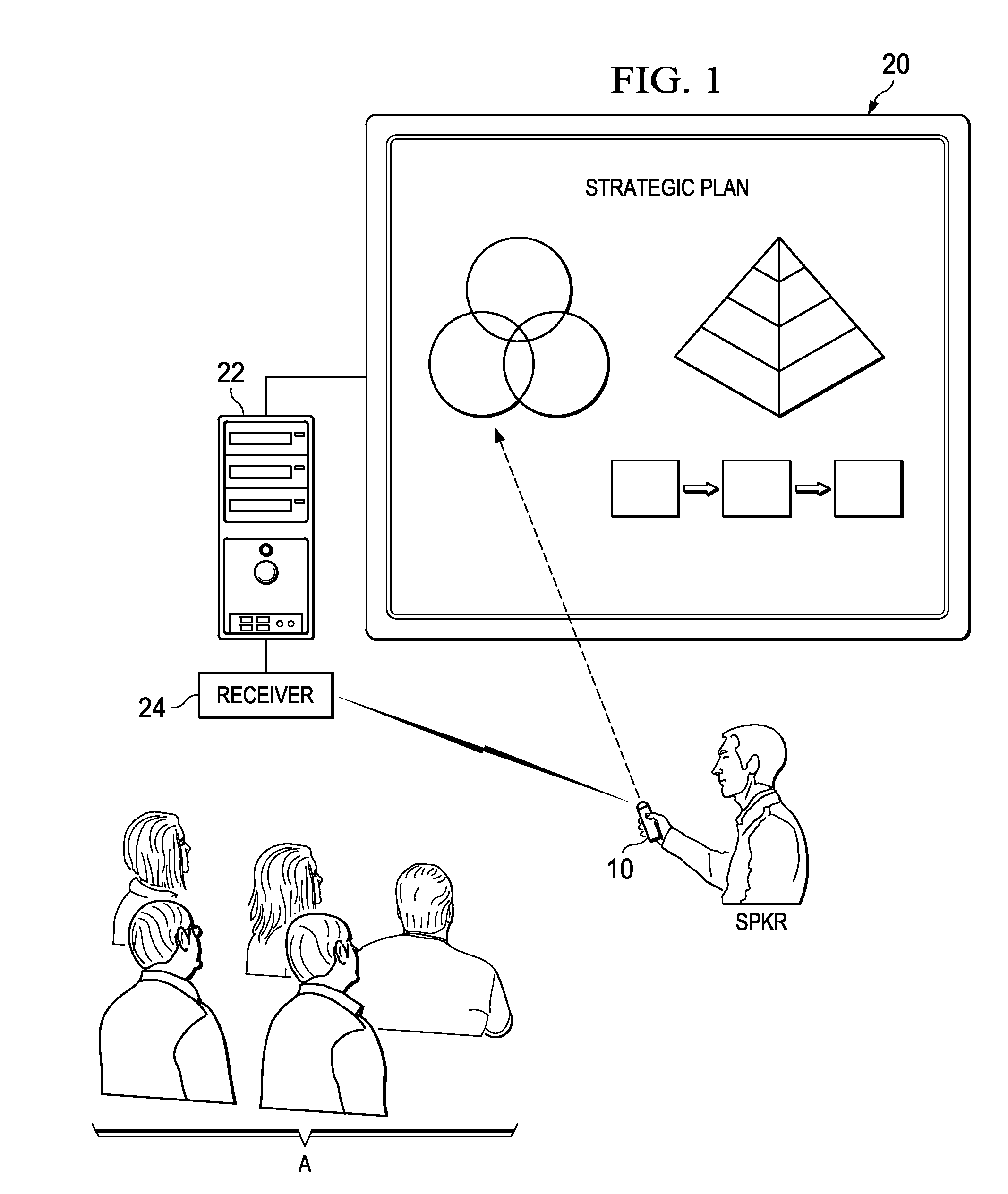
[0052]FIG. 1 illustrates a simplified example of an environment in which embodiments of this invention are useful. As shown in FIG. 1, speaker SPKR is giving a live presentation to audience A, with the use of visual aids. In this case, the visual aids are in the form of computer graphics and text, generated by comput...


PUM


Abstract

An interactive display system including a wireless pointing device including a camera or other video capture system. The pointing device captures images displayed by the computer, including one or more human-imperceptible positioning targets. The positioning targets are presented as patterned modulation of the intensity (e.g., variation in pixel intensity) in a display frame of the visual payload, followed by the opposite modulation in a successive frame. At least two captured image frames are subtracted from one another to recover the positioning target in the captured visual data and to remove the displayed image payload. The location, size, and orientation of the recovered positioning target identify the aiming point of the remote pointing device relative to the display. Another embodiment uses temporal sequencing of positioning targets (either human-perceptible or human-imperceptible) to position the pointing device.

Description

CROSS-REFERENCE TO RELATED APPLICATIONS[0001]This application claims priority, under 35 U.S.C. §119(e), of Provisional Application No. 61 / 314,437, filed Mar. 16, 2010, incorporated herein by this reference.STATEMENT REGARDING FEDERALLY SPONSORED RESEARCH OR DEVELOPMENT[0002]Not applicable.BACKGROUND OF THE INVENTION[0003]This invention is in the field of interactive display systems. Embodiments of this invention are more specifically directed to such display systems, and methods of operating the same, in which the user interacts with displayed content using a remote hand-held device.[0004]The ability of a speaker to communicate a message to an audience is generally enhanced by the use of visual information, in combination with the spoken word. In the modern era, the use of computers and associated display systems to generate and display visual information to audiences has become commonplace, for example by way of applications such as the POWERPOINT presentation software program avai...

Claims


Application Information

Patent Timeline
Patent Type & Authority Patents(United States)
IPC IPC(8): H04N9/47H04N7/18G06F3/038
CPCG06F3/0321G06F3/0346G06F3/03542G06F3/0386H04N9/3182H04N9/3179H04N9/3194G06F3/01G06F3/14G06T1/00
Inventor SOLOMON, YORAMANDERSON, III, ROBERT FINISLI, HONGJUNKALUSH, GREGORY BRIAN
Owner INTERPHASE CORP
Why Eureka
Try Eureka