
Lane change assist system

a technology of assist system and lane change, which is applied in the direction of non-deflectable wheel steering, external condition input parameters, underwater vessels, etc., can solve the problems of difficult to obtain the speed of adjacent vehicles uniformly, and difficulty in ensuring a space margin for controlling the host, and achieve the effect of effective lane change assistan

Inactive Publication Date: 2012-07-10
NISSAN MOTOR CO LTD
View PDF41 Cites 32 Cited by
  • Summary
  • Abstract
  • Description
  • Claims
  • Application Information

AI Technical Summary

Benefits of technology

The present invention provides a lane change assist system that can effectively assist a vehicle in changing lanes, even when there is a small difference in speed between the vehicle and the adjacent vehicle. The system detects the vehicle's speed and the speed of other vehicles around it, and uses a processing unit to set a target lane and determine the appropriate speed range for the vehicle to change lanes. This allows the vehicle to execute the lane change with ease and ensures safety during the process.

Problems solved by technology

However, since this known lane change assist system is arranged to bring the host vehicle speed closer to the adjacent vehicle speed on the target lane before the execution of the lane change, there is a problem that the assist of controlling the host vehicle speed at the vehicle speed of the adjacent vehicle is not an effective assist in a situation that it is difficult to ensure a space margin for controlling the host vehicle to the adjacent vehicle speed of the adjacent vehicle on the target lane due to the existence of a preceding vehicle ahead of the host vehicle on the present traveling lane or that a difference between the host vehicle speed and the adjacent vehicle speed is very small.
Further, in a situation that a plurality of adjacent vehicles are traveling on the target lane while separately having various inter-vehicle distances and vehicle speeds, respectively, it is difficult to obtain the adjacent vehicle speed uniformly.

Method used


Image

  • Lane change assist system
  • Lane change assist system
  • Lane change assist system

Examples


first embodiment

[0028]Referring to FIGS. 1 through 12, there is discussed a first embodiment of a lane change assist system and a method thereof.

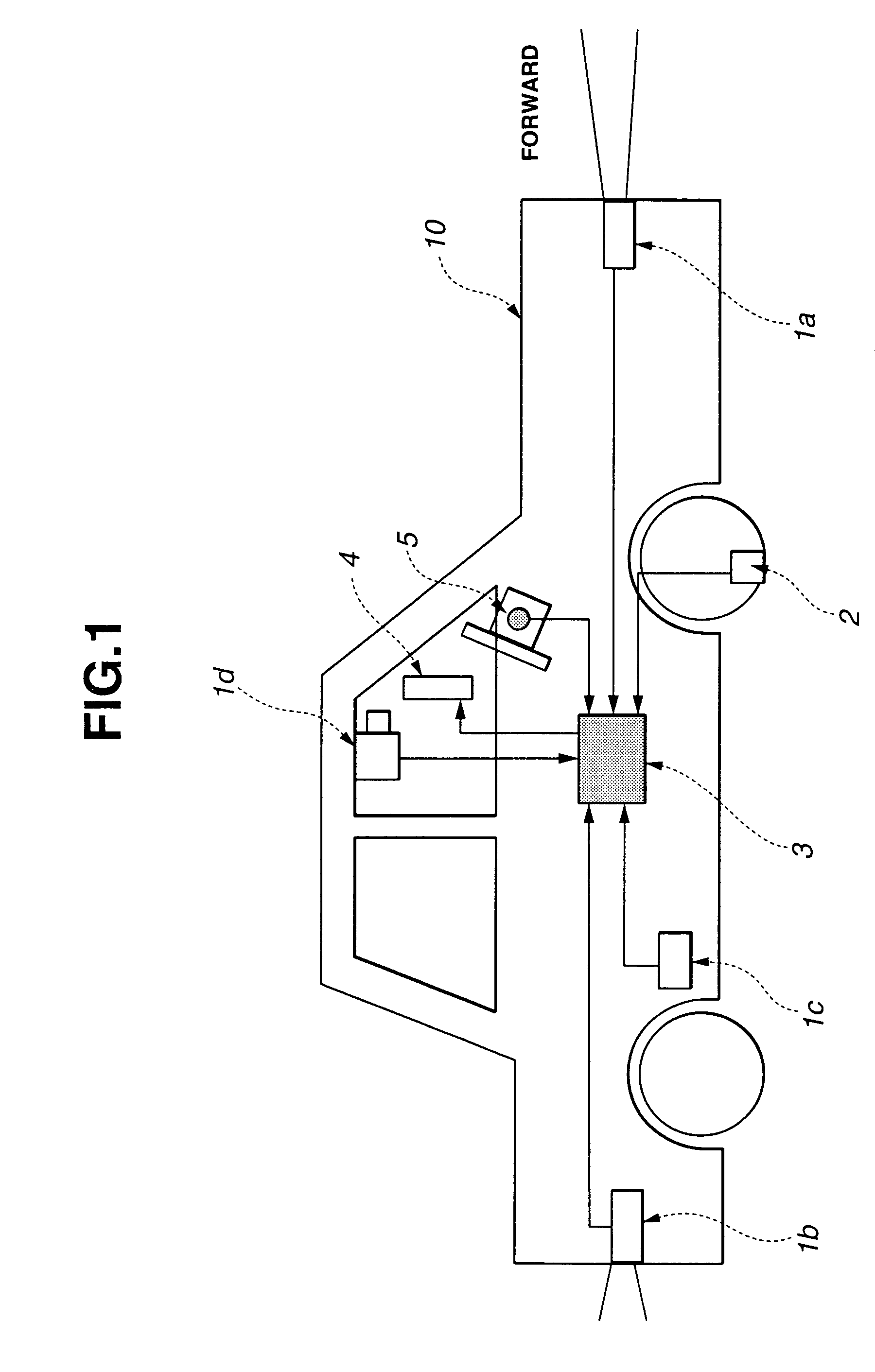
[0029]FIG. 1 is a schematic view of the lane change assist system, which a host vehicle 10 is equipped with. The lane change assist system comprises a forward radar 1a, a rearward radar 1b, a sideward sensor 1c, a lane marker (white line) sensor 1d, a vehicle speed sensor 2, a processing unit 3, a display unit 4, and a turn indicator 5.

[0030]Forward radar 1a is installed at a front portion of host vehicle 10 and measures distances of a plurality of vehicles ahead of host vehicle 10. Rearward radar 1b is installed at a rear portion of host vehicle 10 and measures distances of a plurality of vehicles at the back of host vehicle 10. Sideward sensors 1c are installed at left and right sides of host vehicles, respectively and detect a position of an adjacent vehicle located sideward of host vehicle 10. A radar may be employed as sideward sensors 1c, and an ultr...

second embodiment

[0132]Referring to FIGS. 13 through 16, there is discussed a second embodiment of the lane change assist system according to the present invention.

[0133]FIG. 13 is a schematic view of the lane change assist system which host vehicle 10 is equipped with. The lane change assist system of the second embodiment comprises a forward radar 1a, a rearward radar 1b, a sideward sensor 1c, a lane marker (white line) sensor 1d, a vehicle speed sensor 2, a processing unit 3, a display unit 4, a turn indicator 5, a GPS (Global Positioning System) signal receiver 6, map information database 7, a throttle controller 8, a throttle actuator 9 and an engine 14.

[0134]The lane change assist system of the second embodiment specially comprises GPS signal receiver 6, map information database 7, throttle controller 8, throttle actuator 9 and engine 14 in addition to the arrangement of the first embodiment.

[0135]GPS signal receiver 6 receives a GPS signal and calculates a present position of host vehicle 10 ...

third embodiment

[0163]Referring to FIGS. 17 through 19, there is discussed a third embodiment of the lane change assist system according to the present invention. The construction of the system of the third embodiment is the same as that of the first embodiment.

[0164]FIG. 17 shows a functional block diagram. As shown in FIG. 17, processing unit 3 of the third embodiment further comprises recommended control input producing means (recommend manipulation quantity calculating means) 3e in the form of software. Further, the processing procedure of processing unit 3 of the third embodiment is shown by a flowchart of FIG. 18 wherein a processing of producing a recommended control input (recommended manipulation quantity) is added to as step S207. The processing contents of steps S201 through S206 are completely the same as those of steps S1 through S6, respectively. Therefore the explanation thereof is omitted herein.

[0165]At step S207 in the flowchart of FIG. 18, the processing of producing the recommen...


PUM


Abstract

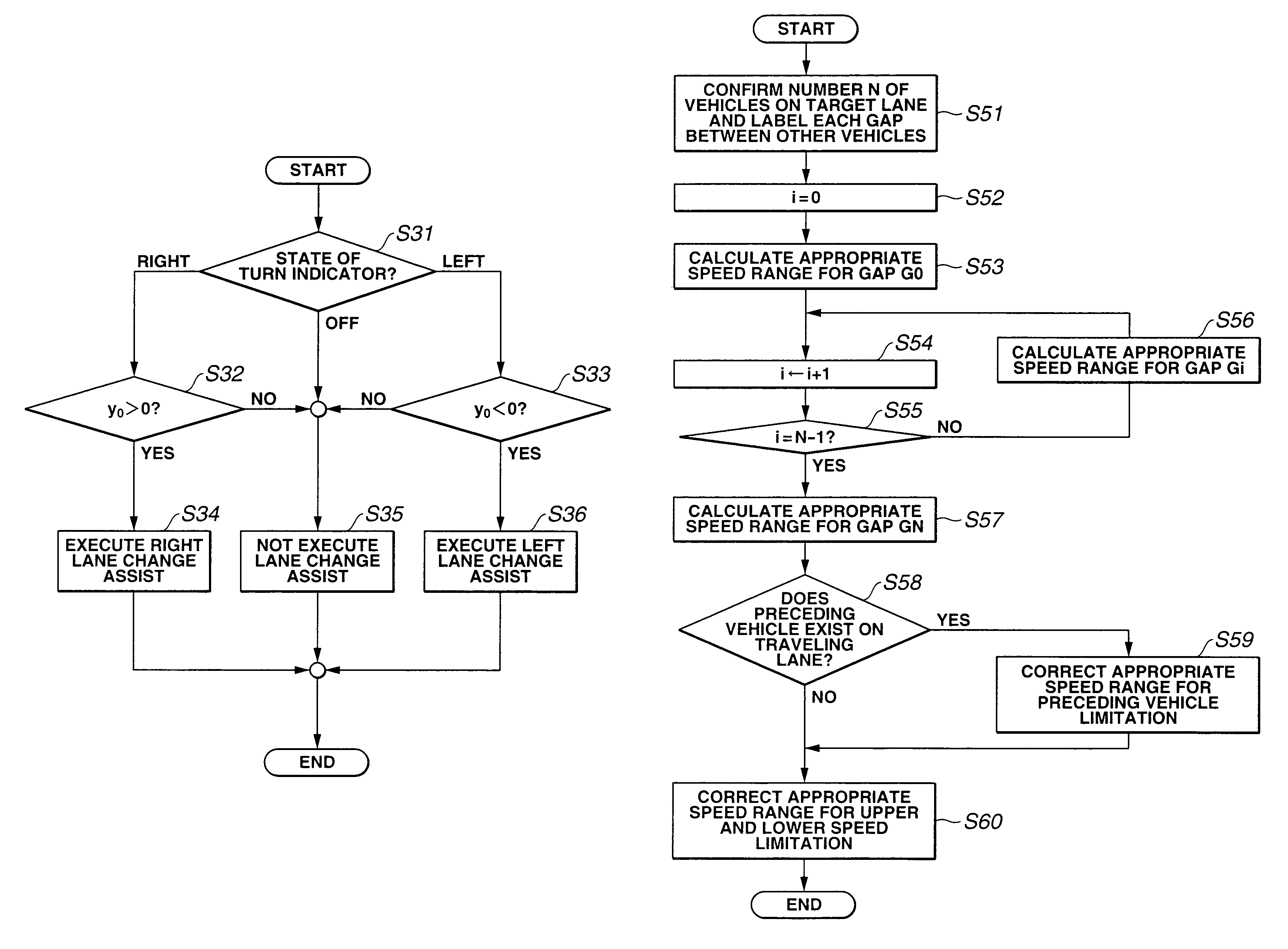
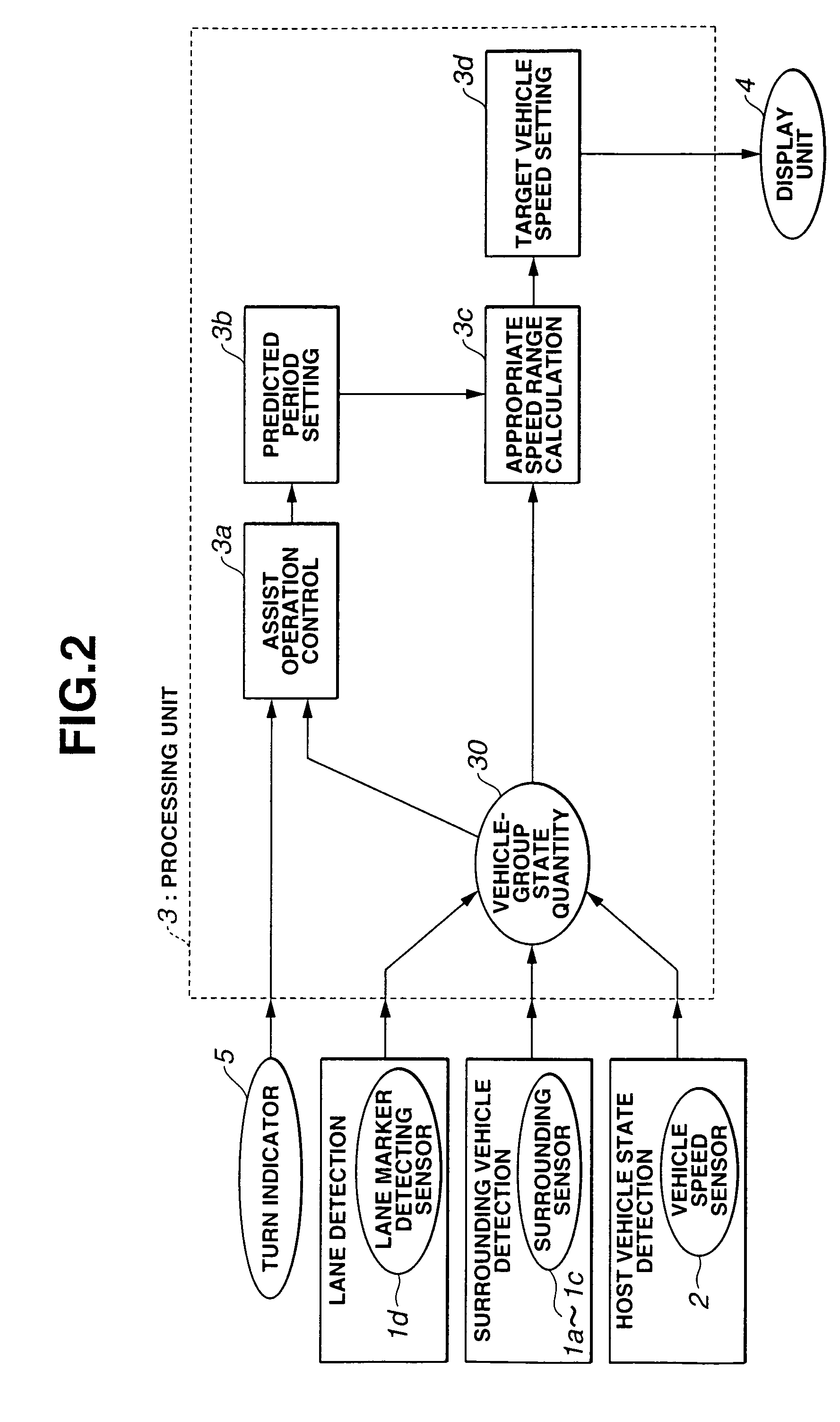
A lane change assist system is comprised of a host vehicle state detecting device that detects a host vehicle traveling condition, a surrounding vehicle detecting device that detects other vehicle located around the host vehicle, a lane detecting device that detects a lane around the host vehicle, and a processing unit. The processing unit is arranged to set a target lane, to determine a period of a lane change assist, to set a predicted period for an evaluation of a lane change to the target lane based on a prediction, to obtain an appropriate speed range during the predicted period for each gap, and to select a target vehicle speed from the appropriate speed range.

Description

BACKGROUND OF THE INVENTION[0001]The present invention relates to a lane change assist system for assisting a lane change of a vehicle and a method thereof.[0002]Japanese Published Patent Application No. 2003-25868 discloses a lane change assist system which facilitates an entering to an adjacent target lane from a present traveling lane and avoids a radical deceleration on the target lane. This lane change assist system is arranged to control a host vehicle speed at a representative vehicle speed of adjacent vehicles on the target lane, to select one adjacent vehicle whose distance to the host vehicle is the smallest distance to a target inter-vehicle distance which is shorter than an inter-vehicle distance set on the target lane as a preceding vehicle on the target lane, and to start a cruise control relative to the newly selected preceding vehicle when a driver manipulates a lane change switch.SUMMARY OF THE INVENTION[0003]However, since this known lane change assist system is ar...

Claims


Application Information

Patent Timeline
Patent Type & Authority Patents(United States)
IPC IPC(8): B60T7/12G06F7/00G06F17/00G05D1/00B60R21/00B60K31/00B60R1/00B60W10/04B60W30/12B60W40/04F02D29/02G08G1/16
CPCB60K31/0008B60W10/04B60W40/04G08G1/16B60W2550/20Y02T10/84B60W50/0097B60W2554/00G08G1/167
Inventor NISHIRA, HIKARUKAWABE, TAKETOSHI
Owner NISSAN MOTOR CO LTD
Learn More