Disk apparatus with resilient member on cam mechanism connecting a main slider to a sub-slider

a resilient member and cam mechanism technology, applied in the direction of instruments, data recording, record carrier guidance, etc., can solve the problems of limiting the thinning of the disk apparatus body, the generation of disk reading errors, and the failure of operation, so as to eliminate the fine vibration of the traverse base and stably read the disk

Inactive Publication Date: 2012-07-10
PANASONIC CORP
View PDF11 Cites 1 Cited by
  • Summary
  • Abstract
  • Description
  • Claims
  • Application Information

AI Technical Summary

Benefits of technology

[0008]If the cam mechanism is provided with a clearance in this manner, the traverse can reliably be displaced, but if a disk whose barycenter is largely deviated is rotated at high speed, fine vibration is generated in the traverse base by the clearance of the cam mechanism, and there is a problem that a disk reading error is generated.
[0009]Hence, it is an object of the present invention to prevent fine vibration of the traverse base when a disk is to be played back in the slot-in type disk apparatus.DISCLOSURE OF THE INVENTION
[0016]According to the present invention, it is possible to eliminate the fine vibration of the traverse base even if a disk whose barycenter is largely deviated is rotated at high speed, and to stably read a disk.

Problems solved by technology

According to such a loading method, however, since the tray or the turntable is required, there is a limit for thinning the disk apparatus body.
In the case of the structure proposed in the patent document 2, however, a cam mechanism for displacing the traverse base between a base body and a lid is generally provided with a clearance so that operation failure is not generated by friction resistance.
If the cam mechanism is provided with a clearance in this manner, the traverse can reliably be displaced, but if a disk whose barycenter is largely deviated is rotated at high speed, fine vibration is generated in the traverse base by the clearance of the cam mechanism, and there is a problem that a disk reading error is generated.

Method used


Image

  • Disk apparatus with resilient member on cam mechanism connecting a main slider to a sub-slider
  • Disk apparatus with resilient member on cam mechanism connecting a main slider to a sub-slider
  • Disk apparatus with resilient member on cam mechanism connecting a main slider to a sub-slider

Examples


embodiment

Preferred Embodiment

[0027]A disk apparatus according to an embodiment of the present invention will be explained below.

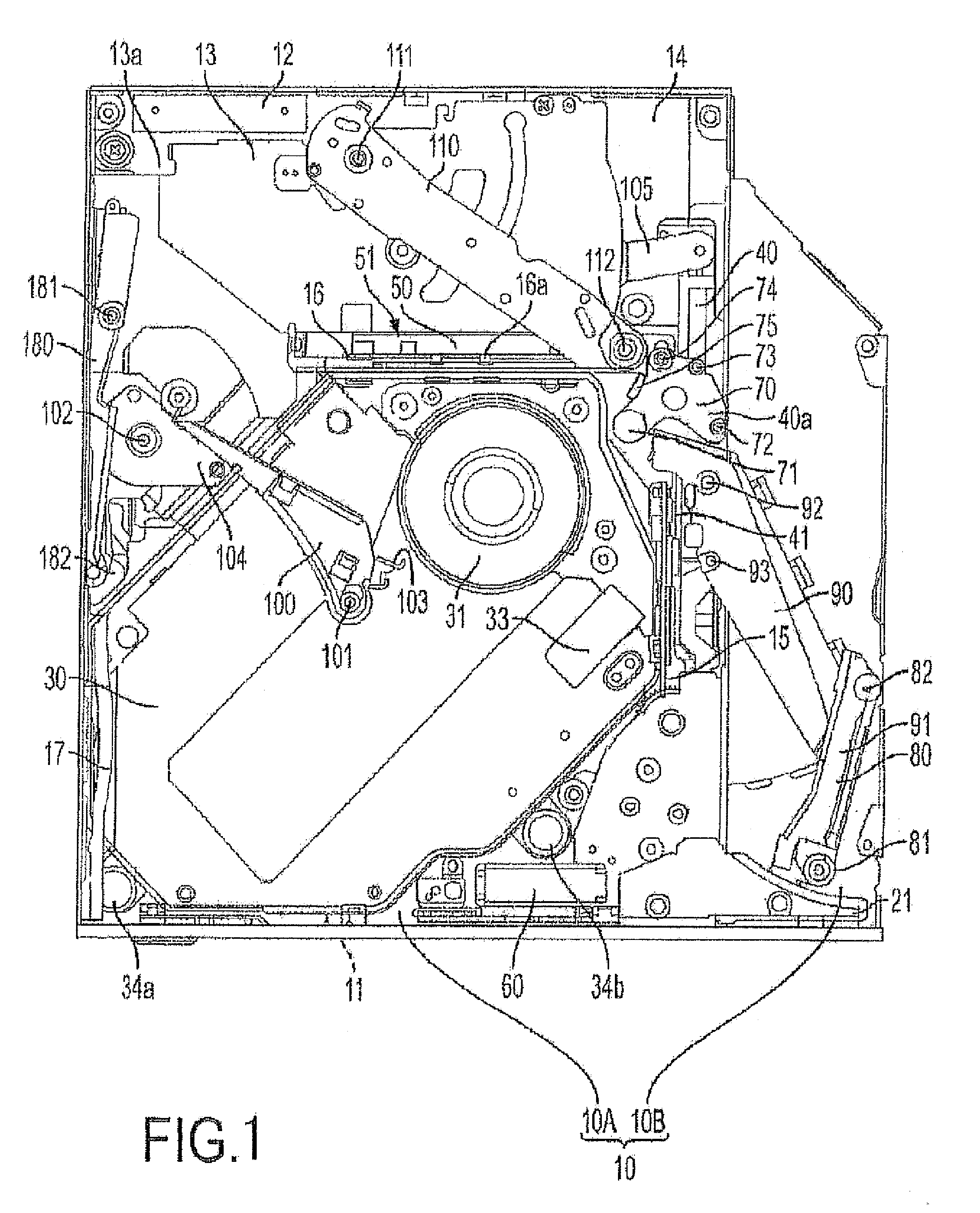
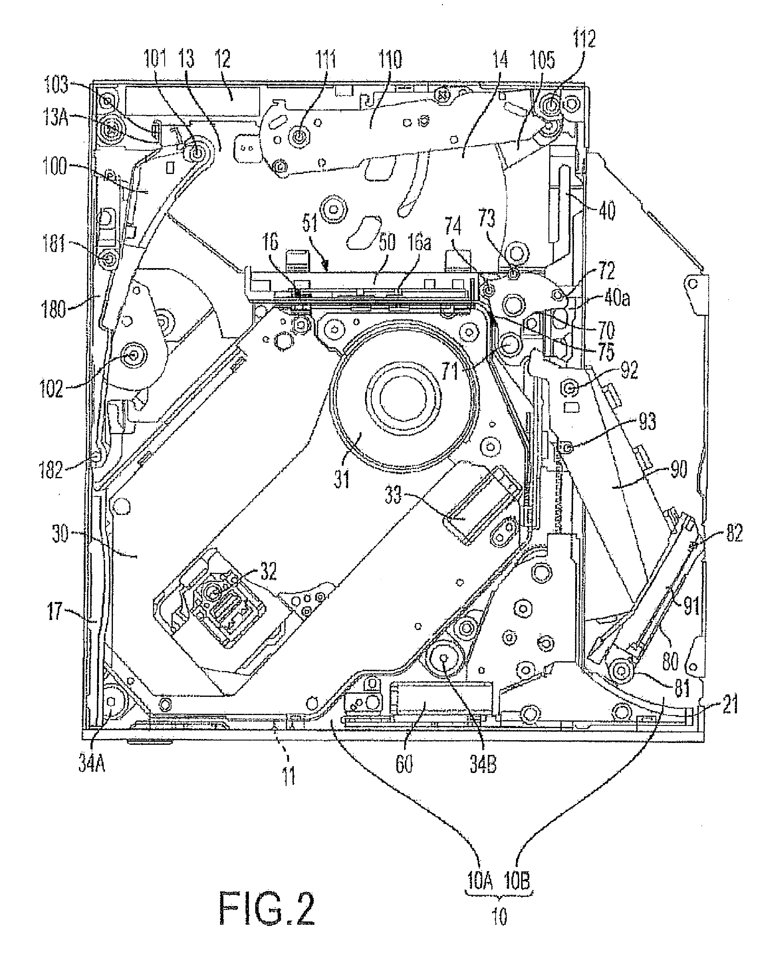
[0028]FIG. 1 is a plan view of a base body of the disk apparatus of the embodiment.

[0029]The disk apparatus of the embodiment includes a chassis outer sheath comprising a base body and a lid. A bezel is mounted on a front surface of the chassis outer sheath. The disk apparatus of the embodiment is a slot-in type disk apparatus in which a disk is directly inserted from a disk inserting opening formed in the bezel. The base body is formed at its front side with an insertion space corresponding to the disk inserting opening into which the disk is directly inserted.

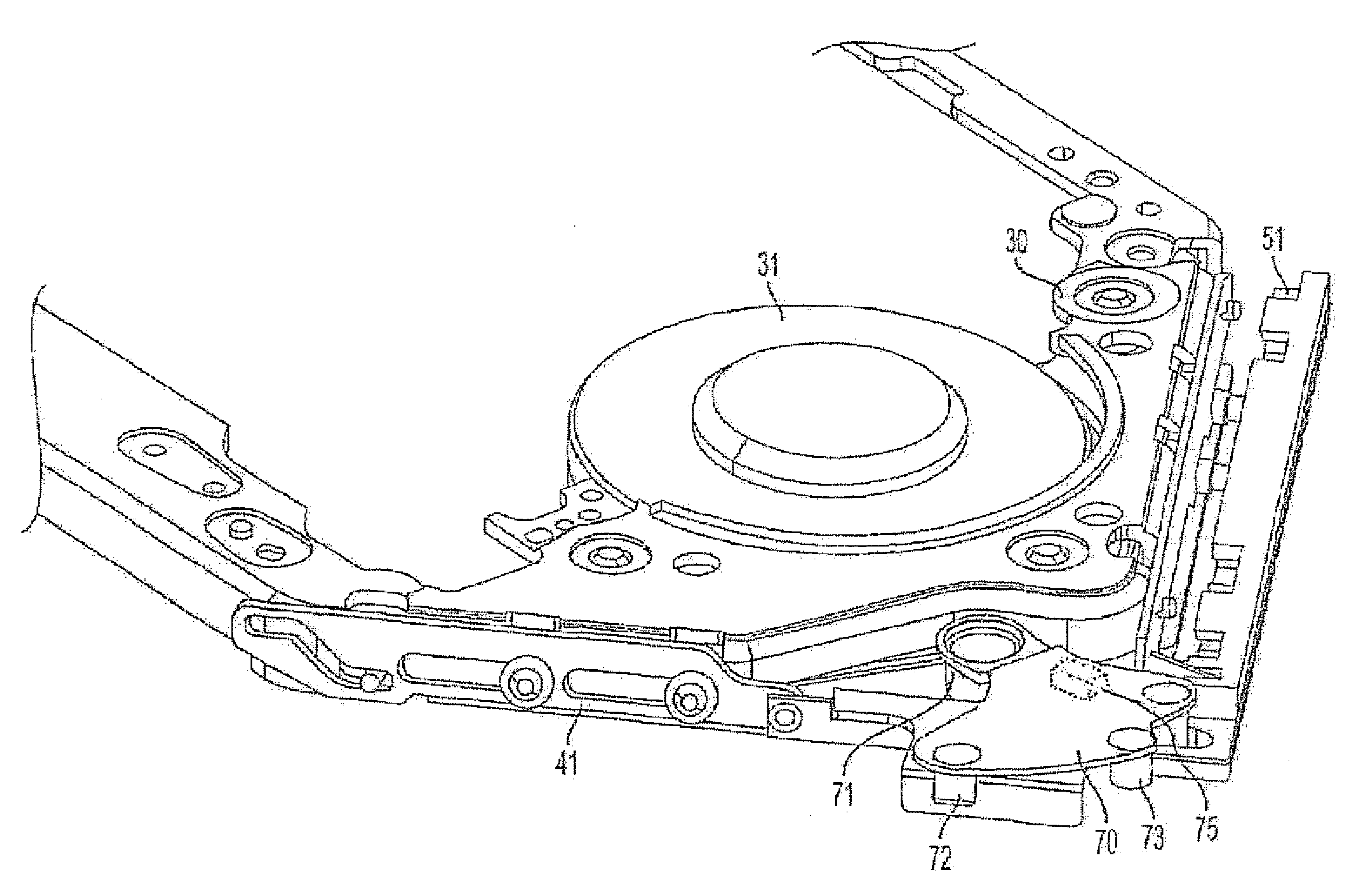
[0030]As shown in FIG. 1, parts which perform a recording function into the disk, a replaying function from the disk and a loading function of the disk are mounted on the base body 10.

[0031]The base body 10 is formed with a deep bottom 10A and a shallow bottom 10B, and the shallow bottom 10B forms a wind port...


PUM

PropertyMeasurementUnit
angleaaaaaaaaaa
movementaaaaaaaaaa
timeaaaaaaaaaa

Abstract

A slot-in type disk apparatus configured to prevent fine traverse base vibration at disk playback. A base body and a lid constitute a chassis outer sheath having a front surface formed with a disk insertion slot. The base body has a traverse base with a spindle motor, a pickup and a driving unit moving the pickup. A cam displaces the traverse base between the base body and the lid. The cam is provided on each of a main slider and a sub-slider. The main slider and the sub-slider are located sideways of the spindle motor and are connected to each other through a cam lever which is moved by the main slider, and the traverse base is displaced by moving the sub-slider. The cam lever has a resilient member which abuts against the traverse base at the time of playback of a disk.

Description

TECHNICAL FIELD[0001]The present invention relates to a disk apparatus for recording or replaying into or from a disk-like recording medium such as a CD and a DVD, and more particularly, to a so-called slot-in type disk apparatus capable of directly inserting or discharging a disk from or to outside.BACKGROUND TECHNIQUE[0002]A loading method is widely employed in conventional disk apparatuses. In this method, a disk is placed on a tray or a turntable, and the tray or the turntable is loaded into an apparatus body. According to such a loading method, however, since the tray or the turntable is required, there is a limit for thinning the disk apparatus body. Hence, recently, there exists a slot-in type disk apparatus in which a disk is directly operated using a lever or the like by a loading motor (e.g., patent document 1).[0003]According to such a slot-in type disk apparatus, however, when a disk is inserted into and ejected from the disk apparatus, it is necessary to lower a spindle...

Claims


Application Information

Patent Timeline
Patent Type & Authority Patents(United States)
IPC IPC(8): G11B17/051G11B7/085G11B15/60
CPCG11B17/051G11B33/08
Inventor WADA, SHINICHI
Owner PANASONIC CORP
Why Eureka
Try Eureka