Structure supporting distribution cable of document reading apparatus

a technology for supporting distribution cables and document reading devices, which is applied in the direction of supporting structure mounting, electrical apparatus, pictoral communication, etc., can solve the problems of blurred document image, inability to read document images smoothly, etc., and achieve the restriction of repulsive stress, restricted repulsive stress, and restricted effect of distribution cabl

Active Publication Date: 2011-12-20
SHARP KK
View PDF5 Cites 2 Cited by
  • Summary
  • Abstract
  • Description
  • Claims
  • Application Information

AI Technical Summary

Benefits of technology

[0013]With such an arrangement structure, the distribution cable passed through from the lead-in opening is bent so as to be pressed against one of the side faces of the pass-through channel by the regulating portion. As a result, in such a state, although repulsive stress that attempts to restore this bent state to the original state acts on a bent portion of the distribution cable, since the pass-through opening of the distribution cable formed by the one side face of the pass-through channel and the regulating portion, and the lead-out opening are disposed so as to be parallel to the document reading direction, the distribution cable is supported at these two locations (that is, the pass-through opening and the lead-out opening which are parallel to the document reading direction) and consequently, the repulsive stress is restricted. In addition, one of the side faces between the pass-through opening and the lead-out opening (that is, the side face against which the distribution cable is pressed by the restoring force due to the repulsive stress) is disposed parallel to the document reading direction, and therefore the repulsive stress of the distribution cable is restricted also by the side face. The repulsive stress of the distribution cable is completely restricted in this area as a result of the distribution cable being supported at two locations, the pass-through opening and the lead-out opening which are parallel to the document reading direction, as well as being abutted against the one side face between the pass-through opening and the lead-out opening. Consequently, when the distribution cable is led out from the lead-out opening, it is not affected by the repulsive stress and is led-out straight along the document reading direction. Furthermore, a fastening portion that fastens the distribution cable is provided at the lead-out opening whose top portion is open so that the distribution cable is completely secured at the lead-out opening, and therefore it is possible to lead out the distribution cable straight along the document reading direction in a stable manner.
[0014]On the other hand, in the vicinity of the distribution cable led out from the support member, the drive wire is disposed along the document reading direction in order to drive the optical scanning unit. However, as described above, the distribution cable of the present invention is also led out so as to be parallel to the drive wire along the document reading direction. Therefore even if the optical scanning unit moves back and forth in the document reading direction so that the led-out portion of the distribution cable undergoes bending displacement in a sideways U shape, such bending displacement occurs along the document reading direction, which does not cause any unexpected contact by the led-out distribution cable to the drive wire.
[0015]In this case, the distribution cable is a parallel duplex cable having a substantially eyeglasses-shaped cross section. Then, the distribution cable led out from the optical scanning unit in a vertical state in which two cores thereof are arranged up and down is passed through from the lead-in opening in the vertical state, is twisted so as to be rotated for 90 degrees after being pressed against the one of the side faces of the pass-through channel by the regulating portion in the vertical state, then is led out from the lead-out opening in a horizontal state in which the two cores thereof are arranged right and left. That is, the distribution cable is twisted for 90 degrees between the pass-through opening and the lead-out opening which are parallel to the document reading direction. Specifically, in terms of the cross section of the distribution cable, the distribution cable is twisted for 90 degrees using as the rotational axis the document reading direction that passes through a substantially central point between the two cores. Therefore, the repulsive force against this rotation (that is, a force to eliminate the twist) does not act in the document reading direction. In other words, although the repulsive force acts on the distribution cable so as to eliminate the twist, the distribution cable led out from the lead-out opening is led out straight in the document reading direction. Moreover, since the fastening portion that fastens the distribution cable is provided in the vicinity of the lead-out opening, the distribution cable is completely secured at the lead-out opening and thereby the repulsive force to the rotation produced due to twisting the distribution cable is also suppressed in this area. Therefore, the distribution cable led out in a horizontal state in which the two cores thereof are arranged right and left is led out straight along the document reading direction in a stable manner without being affected by any stress produced inside the support member that acts on the distribution cable.
[0016]Also in this invention, the optical scanning unit includes a first scanning unit from which the distribution cable is led out, and a second scanning unit that guides light reflected on a document from the first scanning unit to an image reading portion, with the second scanning unit including a pulley that supports and guides the distribution cable led out. In addition, a cable guide is disposed on each side of the pulley. By providing a pulley and cable guides to the second scanning unit in this manner, even if the optical scanning unit moves back and forth in the document reading direction so that the led-out portion of the distribution cable undergoes bending displacement in a sideways U shape, effects by such bending displacement are received by the pulley, and such bending displacement occurs in the document reading direction while the movement thereof being restricted by the cable guide, which does not cause any unexpected contact by the led-out distribution cable to the drive wire. Through this, it is possible to cause the distribution cable to undergo bending displacement along the document reading direction more reliably.
[0017]With the structure supporting a distribution cable of the present invention, the distribution cable passed through from the lead-in opening of the support member is bent so as to be pressed against one of the side faces of the pass-through channel by the regulating portion. Although repulsive stress that attempts to restore this bent state to the original state acts on a bent portion of the distribution cable, since the pass-through opening of the distribution cable formed by the one of the side faces of the pass-through channel and the regulating portion, and the lead-out opening are disposed so as to be parallel to the document reading direction, the distribution cable is supported at these two locations (that is, the pass-through opening and the lead-out opening which are parallel to the document reading direction) and consequently, the repulsive stress is restricted. In addition, one of the side faces between the pass-through opening and the lead-out opening is disposed parallel to the document reading direction, and therefore the repulsive stress of the distribution cable is restricted also by the side face. The repulsive stress of the distribution cable is completely restricted in this area as a result of the distribution cable being supported at two locations, the pass-through opening and the lead-out opening, which are parallel to the document reading direction, as well as being abutted against the one side face between the pass-through opening and the lead-out opening. Consequently, when the distribution cable is led out from the lead-out opening, it is not affected by the repulsive stress and is led out straight along the document reading direction. As a result, it is possible to prevent occurrence of events in which the distribution cable contacts the drive wire of the optical scanning unit due to back and forth movement of the optical scanning unit in the document reading direction, a leakage current is generated via floating capacitance present between the distribution cable and the drive wire, and consequently the light intensity of the lamp may become unstable, or in some cases the distribution cable may be broken as a result of the coating thereof being damaged due to a frictional force produced between it and a pulley holding member.

Problems solved by technology

In addition, it has been also possible that the optical scanning unit 600 does not operate smoothly due to a frictional force produced between the distribution cable 650 and the drive wire 520 so that the read document image becomes blurred.

Method used


Image

  • Structure supporting distribution cable of document reading apparatus
  • Structure supporting distribution cable of document reading apparatus
  • Structure supporting distribution cable of document reading apparatus

Examples


Embodiment Construction

[0034]Hereinafter, embodiments of the present invention will be described in detail with reference to the accompanying drawings.

[0035]Overall Description of the Document Reading Apparatus

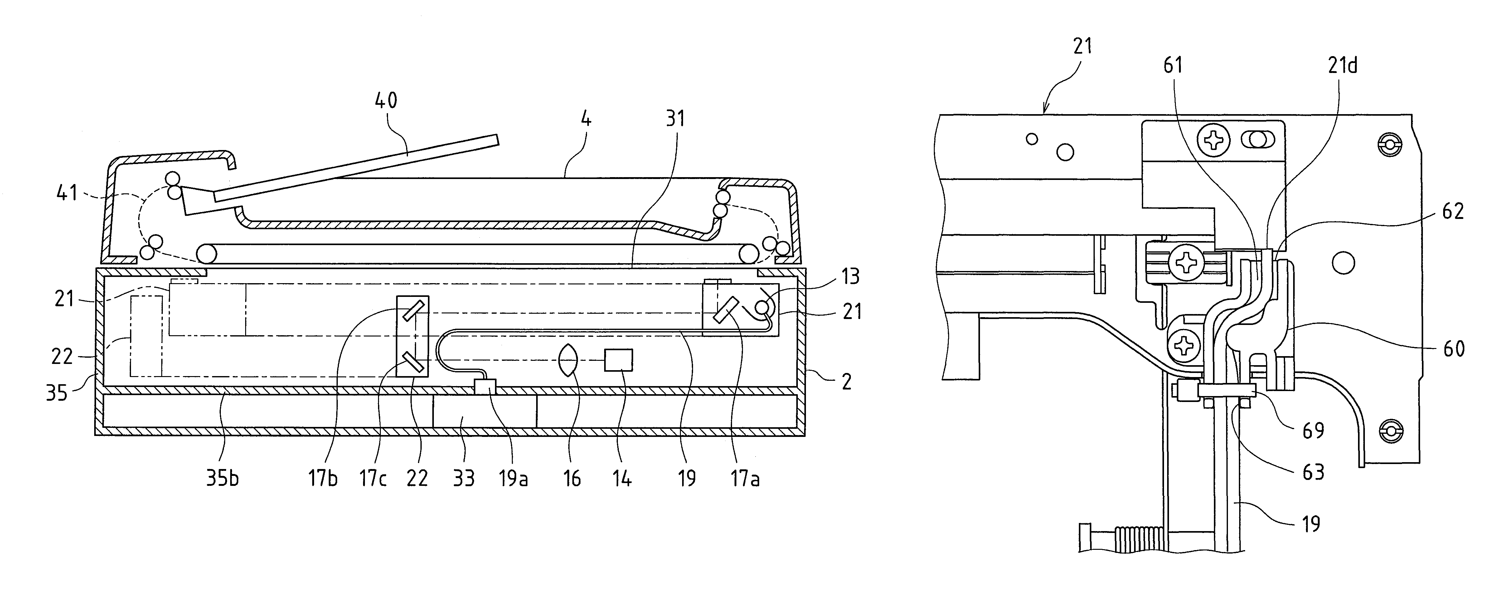
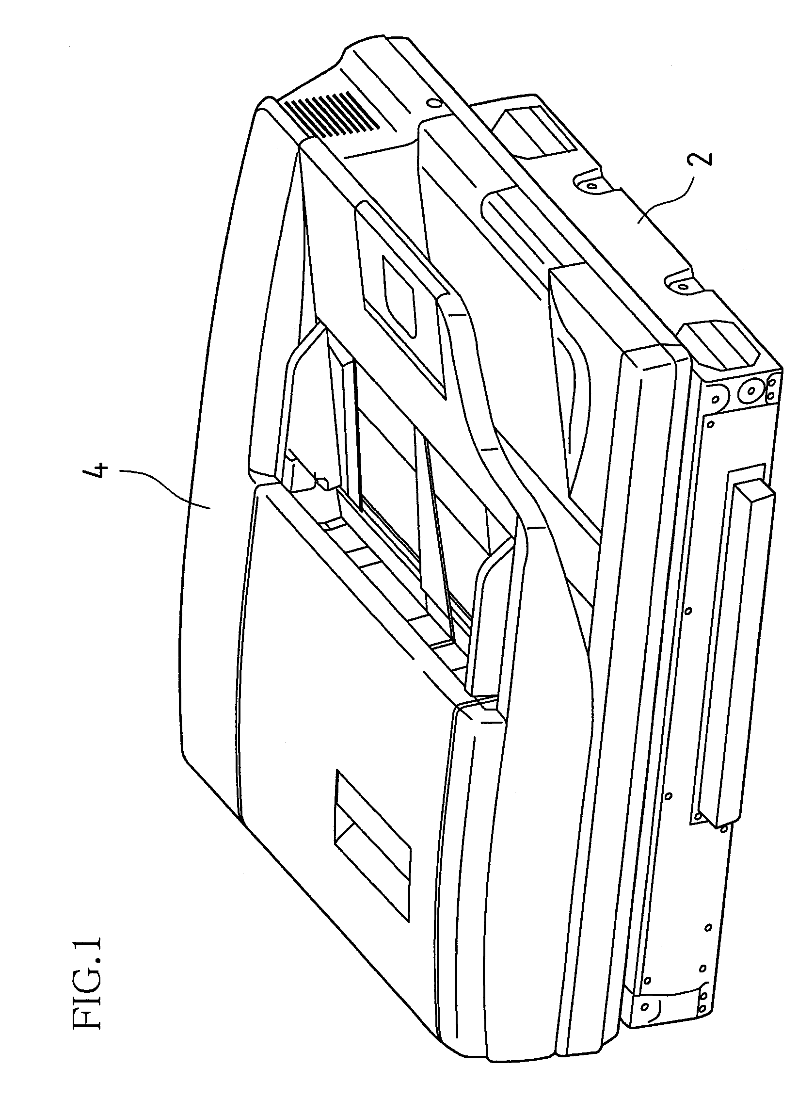
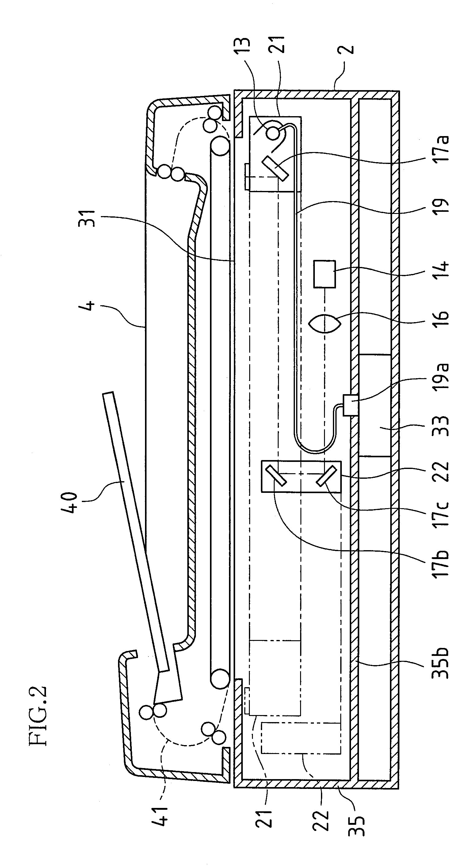
[0036]FIG. 1 shows the entire appearance of a document reading apparatus 2 according to the present embodiment. Also, FIG. 2 is a schematic cross-sectional view of the document reading apparatus 2 shown in FIG. 1.

[0037]On top of the document reading apparatus 2 of the present embodiment, an automatic document feeder (ADF) 4 is provided that automatically transports a document along a document transport path.

[0038]The document reading apparatus 2 includes a document placement table 31 arranged in the top face of a frame 35 that forms an outer frame, a first scanning unit 21, a second scanning unit 22 and an imaging lens 16, image sensing device (CCD) 14, and a drive circuit board 33.

[0039]The first scanning unit 21 includes a light source lamp 13, a first mirror 17a and the like. The light source lam...


PUM


Abstract

An embodiment of the present invention involves a document reading apparatus that includes an optical scanning unit that moves back and forth in a document reading direction so as to read information of a document placed on a document placement table arranged in a top face of a frame by irradiating the document with light emitted from a light source lamp, and a distribution cable connected to the light source lamp. The optical scanning unit includes a support member that leads out and supports the distribution cable connected to the light source lamp in the document reading direction, and the support member includes a regulating member that regulates inclination of the lead-out distribution cable with respect to the document reading direction to support the distribution cable so as to be substantially parallel to the document reading direction.

Description

BACKGROUND OF THE INVENTION[0001]This application claims priority under 35 U.S.C. §119(a) on Japanese Patent Application No. 2007-039797 filed in Japan on Feb. 20, 2007, the entire contents of which are hereby incorporated by reference.[0002]The present invention relates to a document reading apparatus provided with an optical scanning unit that moves back and forth in a document reading direction so as to read information of a document placed on a document placement table arranged in a top face of a frame by irradiating the document with light emitted from a light source lamp, and a distribution cable connected to the light source lamp, and in particular, to a structure supporting the distribution cable.[0003]As schematically shown in FIG. 14, a conventional document reading apparatus is provided with an optical scanning unit 600 that moves back and forth in a document reading direction (hereinafter also referred to as a “sub-scanning direction”) X so as to read information of a do...

Claims


Application Information

Patent Timeline
Patent Type & Authority Patents(United States)
IPC IPC(8): H04N1/04H05K7/14
CPCH04N1/1013H04N1/1026
Inventor OKADA, TOMOHIKOSUTO, YASUHIROYOSHIMOTO, MITSUHARUTANAKA, KENJI
Owner SHARP KK
Why Eureka
Try Eureka