Hoop molding method

a molding method and hoop technology, applied in the direction of casings/cabinets/drawers, electrical apparatus construction details, casings/cabinets/drawers details, etc., can solve the problem of difficult to cause plural molding parts, and achieve the effect of suppressing the deformation of the other portions of the frame portions

Active Publication Date: 2009-03-03
KK TOKAI RIKA DENKI SEISAKUSHO
View PDF4 Cites 1 Cited by
  • Summary
  • Abstract
  • Description
  • Claims
  • Application Information

AI Technical Summary

Benefits of technology

[0019]For this reason, plural parent materials do not have to be used when disposing the plural molded portions. Because the plural molded portions can be formed from one parent material in this manner, the step of a worker arranging by hand the molded portions inside the die after cutting away the molded portions from plural parent materials can be eliminated.
[0020]In the first aspect of the invention, the method may include making the rigidity of at least one of the connection portions and portions of the frame portions in the vicinity of where the frame portions are connected to the connection portions to be lower than that of other portions of the frame portions.
[0021]In the hoop molding method of the first aspect of the invention, because the rigidity of at least one of the connection portions and portions of the frame portions in the vicinity of where the frame portions are connected to the connection portions is made lower than that of other portions of the frame portions, the portions with low rigidity are elastically deformed when the molded portions linked to the connection portions are displaced after the bending, and deformation of the other portions of the frame portions can be effectively suppressed.
[0022]Thus, the molded portions linked to the connection portions can be reliably displaced toward the bent molded portions without inadvertently causing the other portions of the frame portions to be deformed.
[0029]For this reason, in the hoop molding method pertaining to the invention, the hoop molding can essentially be handled in the same manner as hoop molding resulting from one parent material when disposing the molded portions inside the die for molding resin, even in a structure where plural molded portions face each other in the thickness direction of the one parent material. For this reason, the step of arranging and disposing the molded portions in a die for molding resin after the molded portions have been cut away from the parent materials can be eliminated.

Problems solved by technology

However, because hoop molding has a structure where the band-like base material is punched and the molded portions are molded in the frame portions, it is extremely difficult to cause plural molded portions to face each other in the thickness direction of the base material.

Method used


Image

  • Hoop molding method
  • Hoop molding method
  • Hoop molding method

Examples


Embodiment Construction

Configuration of the Embodiment

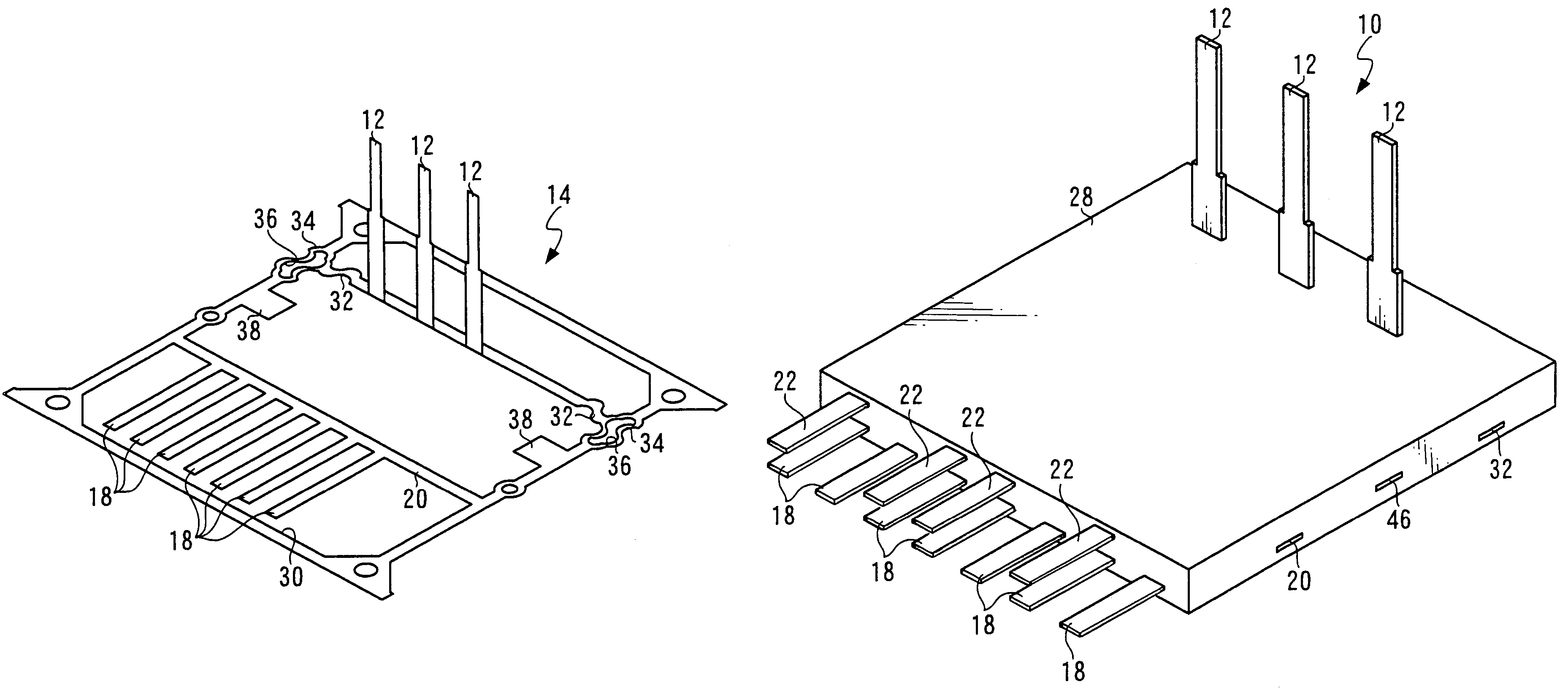
[0045]A connector 10 that is formed by a hoop molding method pertaining to the embodiment of the invention is shown in perspective view in FIG. 9.

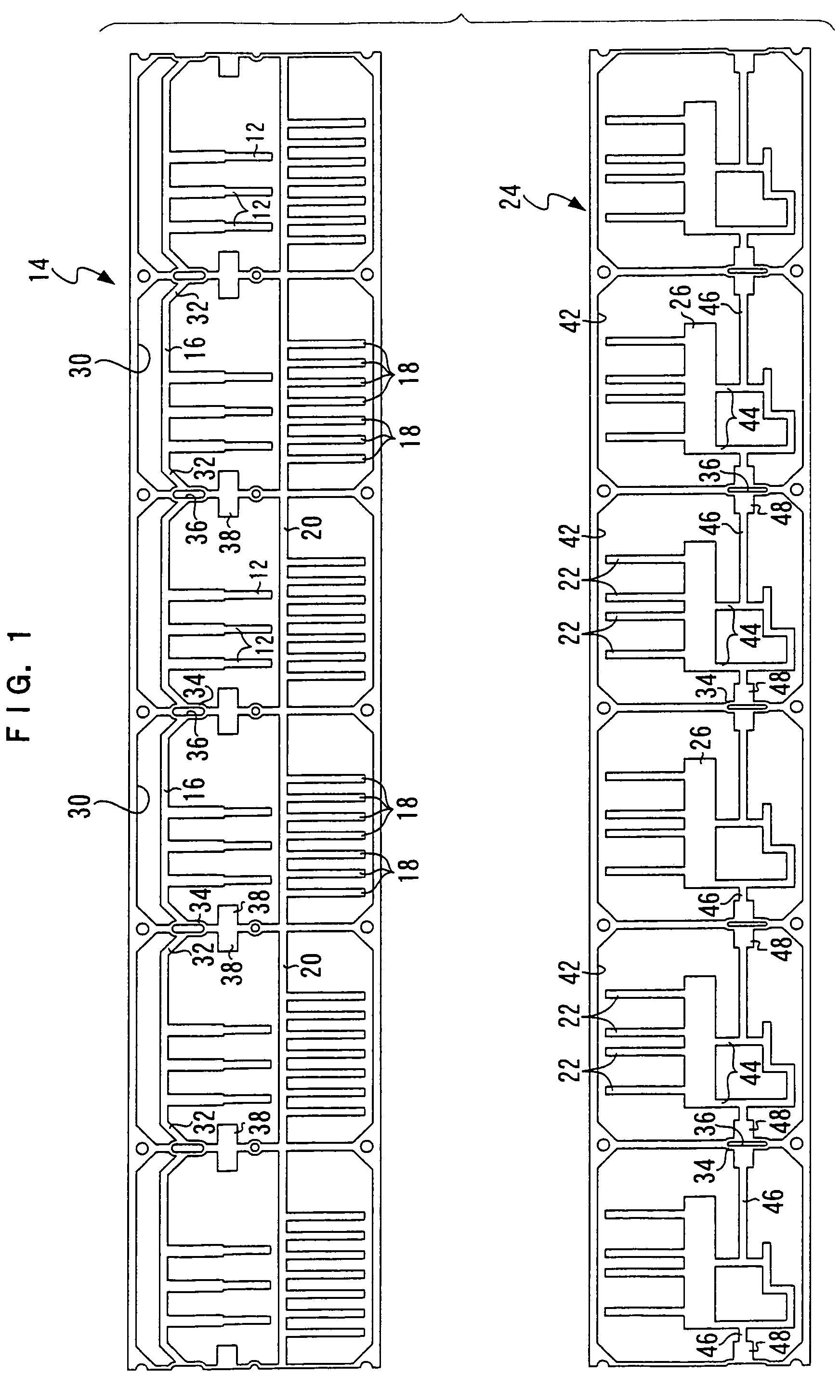
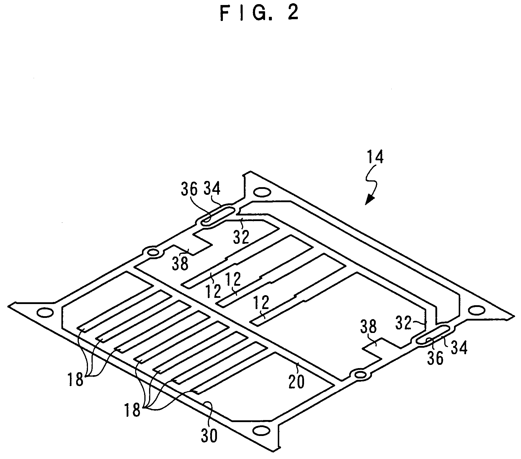
[0046]As shown in FIG. 9, the connector 10 includes plural terminals 12, each of which is a part of a molded portion. The plural terminals 12 are formed by punching, by pressing or the like, a long band-like hoop material 14 serving as a parent material shown in FIG. 1.

[0047]As shown in FIG. 1, the terminals 12 are formed at predetermined intervals along the longitudinal direction of base portions 16, which are long in the longitudinal direction of the hoop material 14, at longitudinal-direction intermediate portions of the base portions 16. Consequently, the terminals 12 are electrically connected, via the base portions 16, at their base end sides.

[0048]As shown in FIG. 3, the terminals 12 are bent toward one side in the thickness direction of the hoop material 14 around the portions where the terminals 12 a...


PUM

PropertyMeasurementUnit
widthaaaaaaaaaa
thicknessaaaaaaaaaa
lengthaaaaaaaaaa

Abstract

A hoop molding method comprises forming, in the frame portions, connection portions that link, to the frame portions, at least one molded portion of the at least one bent molded portion or at least another molded portion other than the at least one bent molded portion such that it is displaceable in a direction toward another molded portion along the width direction of the parent material, and displacing the at least one molded portion of the at least one bent molded portion or the at least another molded portion other than the at least one bent molded portion toward the another molded portion after the bending.

Description

CROSS-REFERENCE TO RELATED APPLICATION[0001]This application claims priority under 35 USC 119 from Japanese Patent Application No. 2004-350384, the disclosure of which is incorporated by reference herein.BACKGROUND OF THE INVENTION[0002]1. Field of the Invention[0003]The present invention relates to a hoop molding method, which is one aspect of a molding method for embedding at least some of molded parts such as metal in a synthetic resin material.[0004]2. Description of the Related Art[0005]Electronic parts such as connectors oftentimes have a structure where some of their metal parts are embedded in a synthetic resin. So-called “hoop molding” is one aspect of a method of molding parts in which some of the metal parts are embedded in the synthetic resin material (for an example of hoop molding, see Japanese Patent Application Publication (JP-A) No. 2001-52556, which is described below).[0006]In hoop molding, a pressing machine and a bending machine are arranged along the longitudin...

Claims


Application Information

Patent Timeline
Patent Type & Authority Patents(United States)
IPC IPC(8): H01R43/00
CPCB29C45/14221B29C45/14639H01R43/24B29C45/14016Y10T29/4922Y10T29/49218Y10T29/49121B29C2045/14254
Inventor SUZUKI, KOJIMIYAKE, FUSATOMO
Owner KK TOKAI RIKA DENKI SEISAKUSHO
Why Eureka
Try Eureka