Screw pump and method of use

a screw pump and screw technology, applied in the direction of machines/engines, liquid fuel engines, positive displacement liquid engines, etc., can solve the problems of reducing the effectiveness of the pump in flood control operations, restricting the location where the conventional pump may be used, and not being suitable for displacing

Active Publication Date: 2022-01-06
KEATCH RICHARD WILLIAM
View PDF0 Cites 1 Cited by
  • Summary
  • Abstract
  • Description
  • Claims
  • Application Information

AI Technical Summary

Benefits of technology

[0007]It is an object of an aspect of the present invention to obviate or...

Problems solved by technology

Conventional Archimedes' screw pumps are not suitable for displacing flood water from all low-lying river types.
The challenging conditions posed by swollen rivers under turbulent flow flood conditions can also restrict the location that co...

Method used


Image

  • Screw pump and method of use
  • Screw pump and method of use
  • Screw pump and method of use

Examples


Embodiment Construction

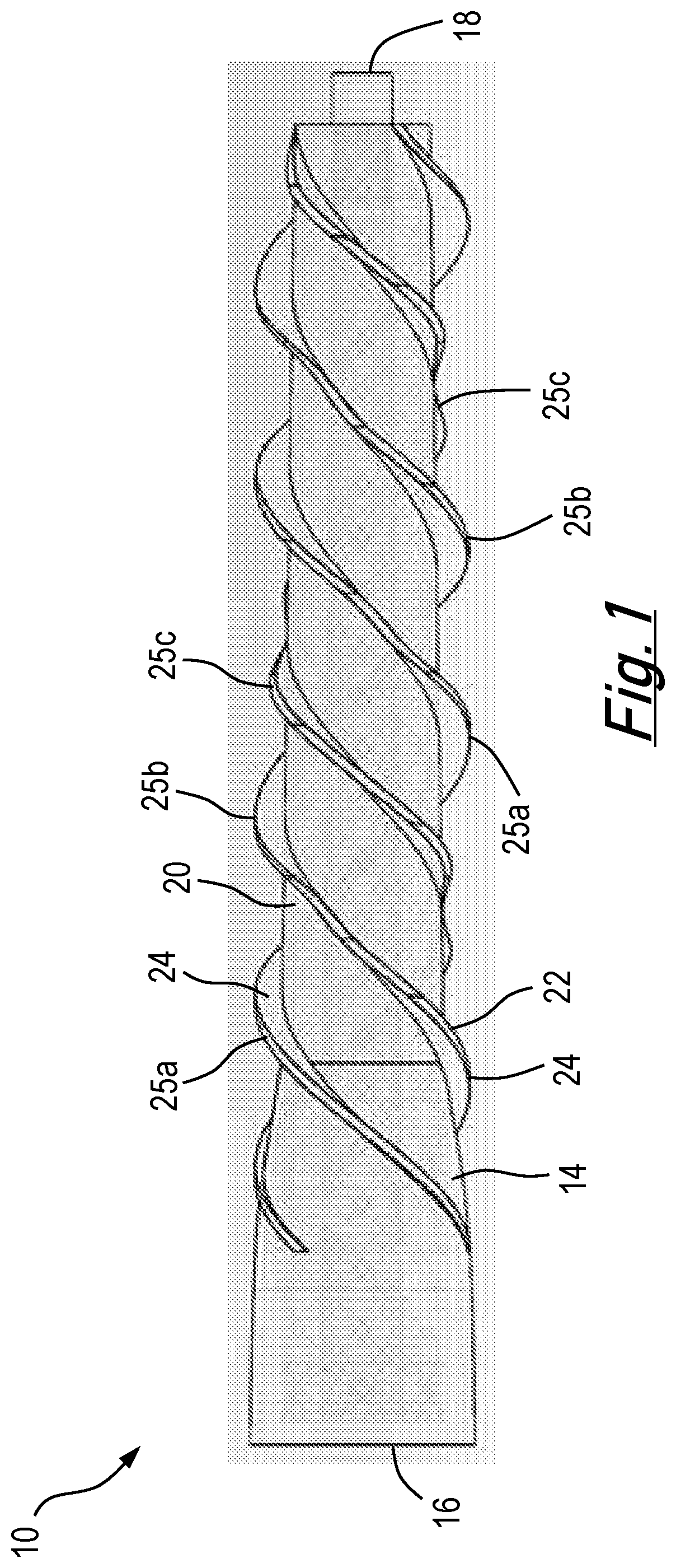
[0088]FIG. 1 presents a screw pump apparatus in accordance with an embodiment of the present invention. The apparatus 10 comprises a body 14, a fluid inlet 16 and a fluid outlet 18. The body 14 has a generally cylindrical outer surface 20 and an outer screw 22 formed from a plurality of helical blades 24 located on the outer surface 20. The blades 24 may be fixed to or integral with the outer surface 20.

[0089]The apparatus 10 is configured to rotate around its longitudinal axis when a fluid passes over the outer surface 20 and the outer screw 22. In this example three blades 25a, 25b and 25c are located on the outer surface 20 in a helical threaded arrangement.

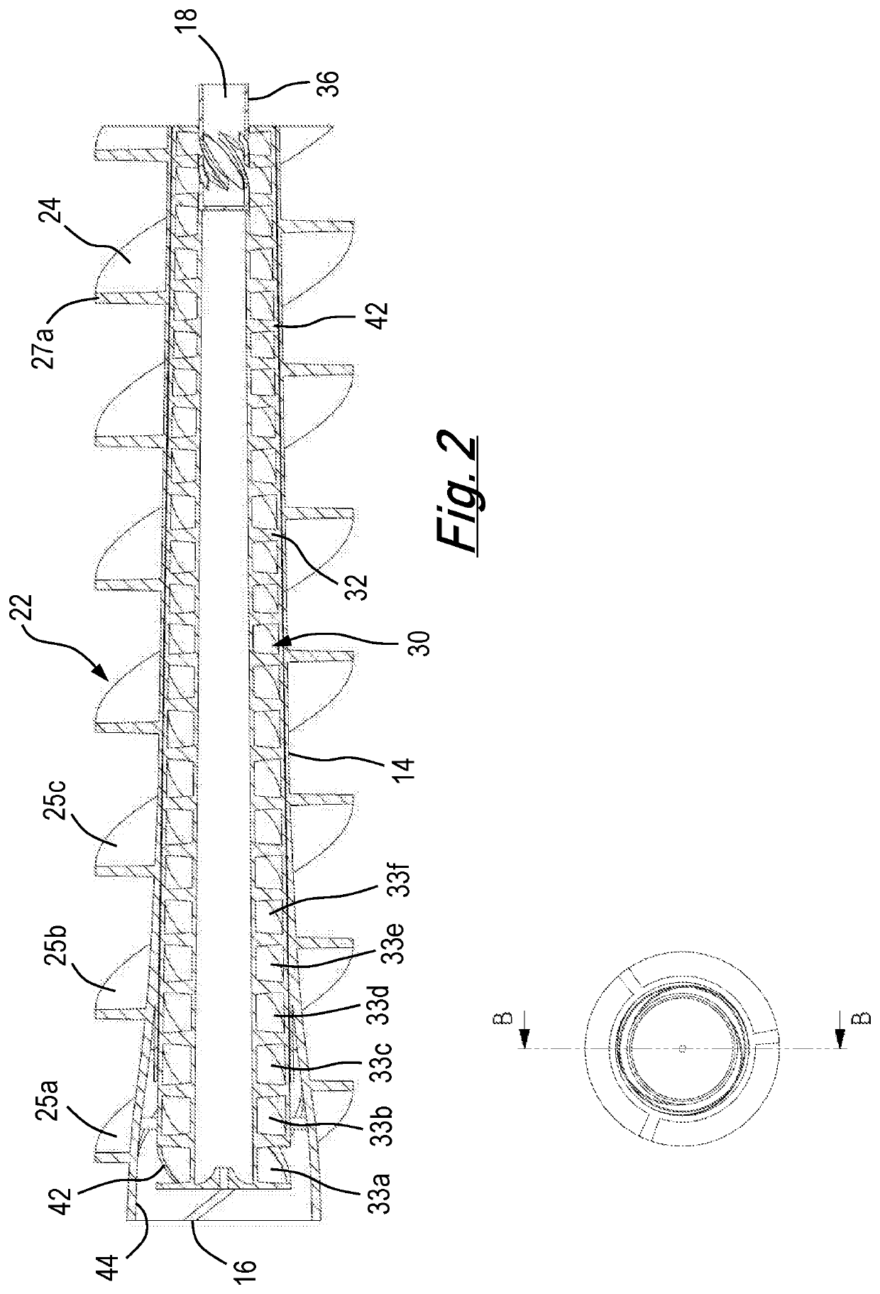
[0090]FIG. 2 shows a cross-sectional view of the apparatus of FIG. 1 along line B-B′. As best shown in FIG. 2 an inner screw 30 is located inside the body 14. The inner screw 30 is configured to be in fluid communication with the fluid inlet via fluid inlet channel 16 and fluid outlet 18. The fluid inlets are openings around t...


PUM


Abstract

The invention provides a fluid pump apparatus comprising a fluid inlet, a fluid outlet, a screw member and a rotatable pump member. The screw member has at least one helical screw blade configured to be rotated by a fluid flow stream and the rotatable pump member is in fluid communication with the fluid inlet and/or fluid outlet.

Description

[0001]The present invention relates to fluid pump systems, in particular positive displacement pump systems. Aspects of the invention include a method of pumping fluids that finds particular application in displacing water for farmland irrigation and during flood control operations.BACKGROUND TO THE INVENTION[0002]Screw pumps such as Archimedes' screw pumps are well-known. These pumps comprise a threaded screw of helical blades mounted on a central shaft. Typically, the threaded screw is mounted inside a cylindrical tube which is open at both ends. The shaft is rotated using either a hand crank or an electric motor.[0003]In use, the Archimedes' screw pump is inclined to the horizontal where one end is submerged underwater and an elevated end rises above the level of the water. As the threaded screw revolves water or other pumpable liquid / material is repeatedly scooped into the lower open end of the screw and forms a series of wells of water in the spaces between the surface of the i...

Claims


Application Information

Patent Timeline
IPC IPC(8): F04B19/12F04B19/06
CPCF04B19/12F04B19/06F04D3/02F04D13/043F05D2240/243A01G25/00F03B17/00F04C2/00F04C7/00F04D13/04F04D31/00Y02E10/20
Inventor KEATCH, RICHARD WILLIAM
Owner KEATCH RICHARD WILLIAM
Why Eureka
Try Eureka