Electrical connector

a technology of electrical connectors and solder balls, which is applied in the direction of coupling contact members, fixed connections, coupling device connections, etc., can solve the problems of unsatisfactory retaining and fixing functions of solder balls, poor electrical connections, and unaddressed needs in the art. , to achieve the effect of improving the soldering performance of electrical connectors, facilitating melting of solder balls, and breaking the surface tension of solder balls

Active Publication Date: 2012-07-17
LOTES
View PDF9 Cites 10 Cited by
  • Summary
  • Abstract
  • Description
  • Claims
  • Application Information

AI Technical Summary

Benefits of technology

[0010]In one aspect, the present invention provides an electrical connector, which is configured to not only desirably retain and fix the solder ball to prevent the solder ball retained by the terminal from sliding down or falling off, but also prevent an open solder connection of the solder ball from happening, so as to improve the soldering effect.
[0012]As compared with the prior art, among other things, the electrical connector of the present invention is configured such that each of the first retaining arms respectively has a hook portion extending towards the retaining hole, the two hook portions fasten and fix the solder ball, so as to prevent the solder ball from sliding or falling off due to an external force; the second retaining arm is disposed inclined towards the retaining hole, and thus can break the surface tension of the solder ball, so as to facilitate melting of the solder ball, and at the same time, the second retaining arm inclinedly penetrates into the molten solder ball due to an elastic restoring force thereof, thereby improving the soldering performance of the electrical connector.

Problems solved by technology

1. Since the two clamps are in the shape of a flat plate, and no fixing structure is disposed between the two clamps to prevent the solder ball from sliding down, the solder ball retained in the solder ball fixing device may slide down between the two clamps or fall off due to a large external force, thereby resulting in that the function of retaining and fixing the solder ball is not desirable.
2. Since the second retaining portion is vertically disposed, and the solder ball may have a surface tension, the second retaining portion cannot break the surface tension of the solder ball when the solder ball is melted by heating, and as a result, the solder ball is only softened, but cannot be completely melt and bonded to the first retaining portion and the second retaining portion, which may easily lead to an open solder connection or a cold solder joint, thereby resulting in poor electrical connection.
Therefore, a heretofore unaddressed need exists in the art to address the aforementioned deficiencies and inadequacies.

Method used


Image

  • Electrical connector
  • Electrical connector
  • Electrical connector

Examples


Embodiment Construction

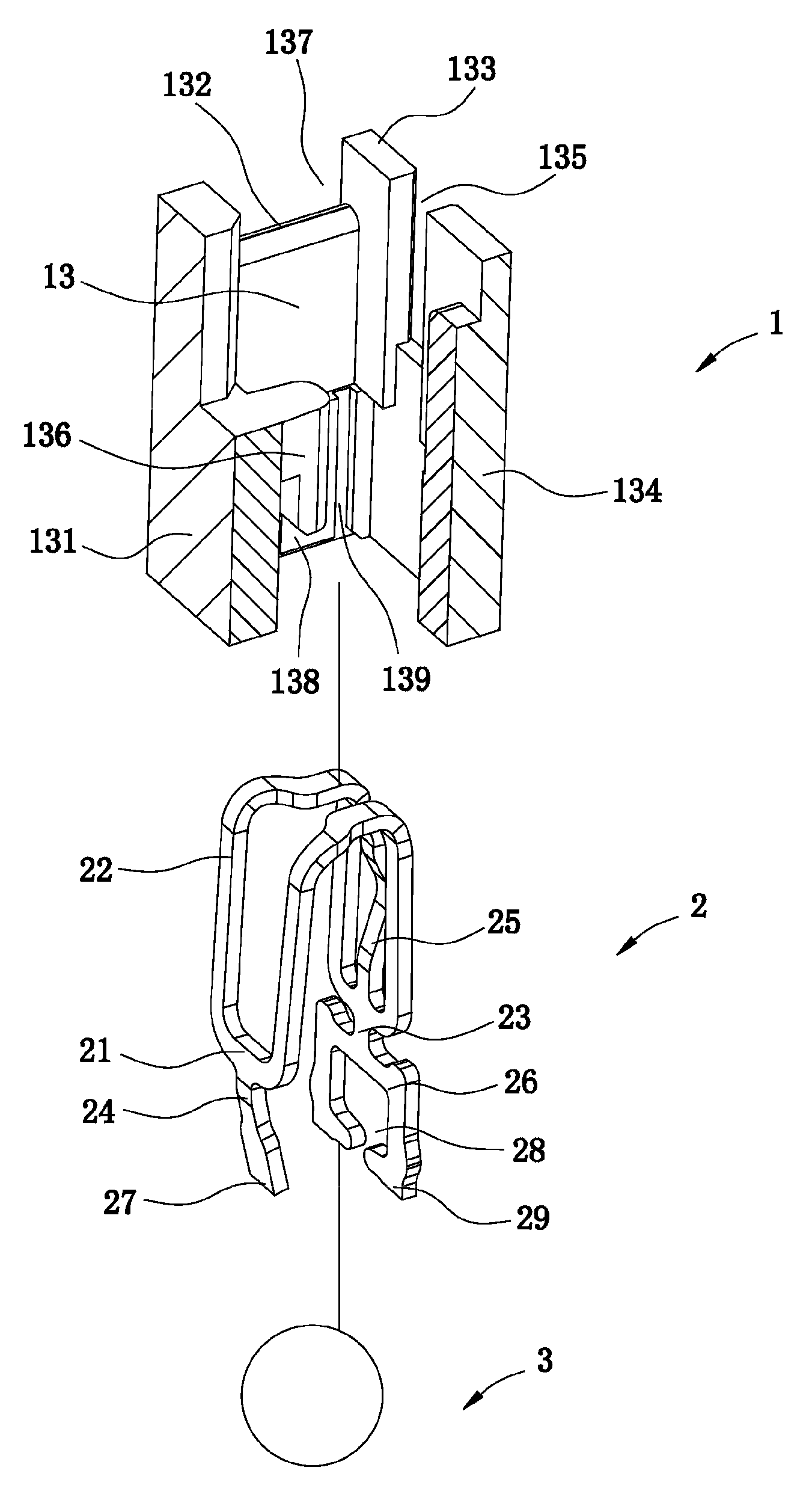
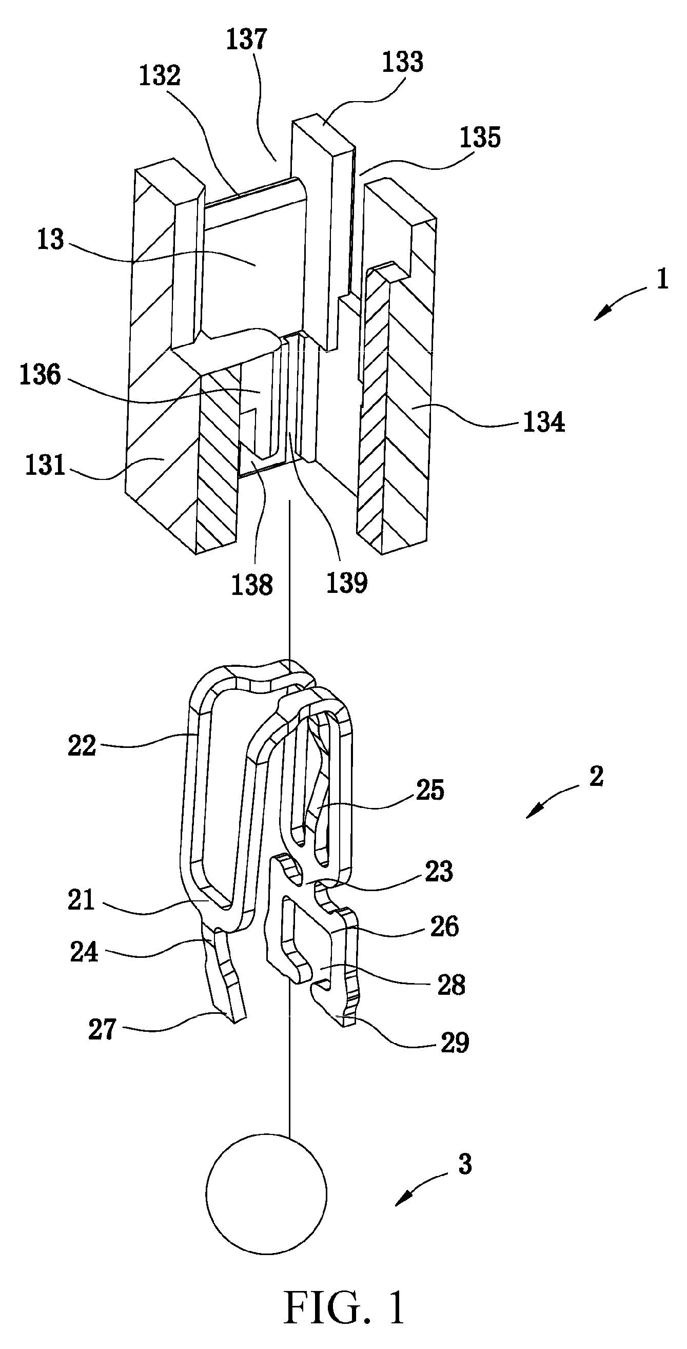
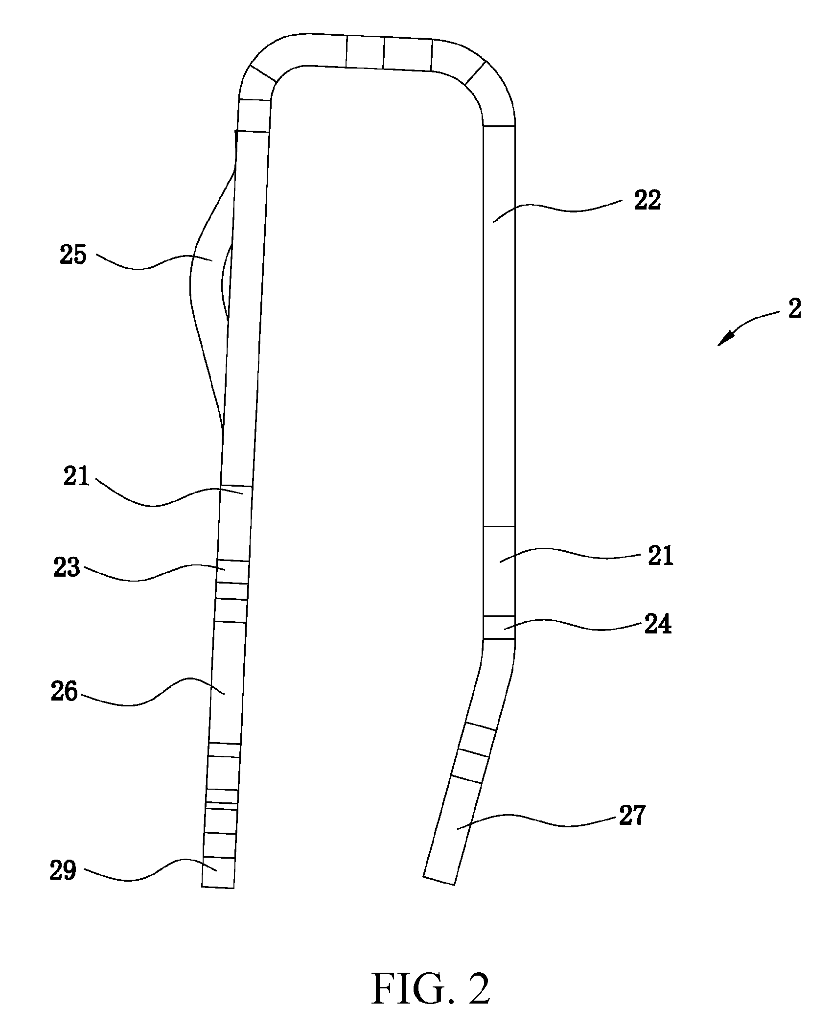
[0020]The present invention is more particularly described in the following examples that are intended as illustrative only since numerous modifications and variations therein will be apparent to those skilled in the art. Various embodiments of the invention are now described in detail. Referring to the drawings, FIGS. 1-5, like numbers, if any, indicate like components throughout the views. As used in the description herein and throughout the claims that follow, the meaning of “a”, “an”, and “the” includes plural reference unless the context clearly dictates otherwise. Also, as used in the description herein and throughout the claims that follow, the meaning of “in” includes “in” and “on” unless the context clearly dictates otherwise. Moreover, titles or subtitles may be used in the specification for the convenience of a reader, which shall have no influence on the scope of the present invention. Additionally, some terms used in this specification are more specifically defined belo...


PUM


Abstract

An electrical connector includes an insulating body, having at least one receiving housing running through the insulating body; at least one conductive member, comprising a contact portion disposed in the receiving housings, and has a middle part higher than two ends; a pair of first retaining arms, extending downwards from one end of the contact portion, wherein a retaining hole is formed between the two arms, and each of the two arms has a hook portion extending towards the retaining hole; a second retaining arm, extending downwards from the other end of the contact portion, wherein the second retaining arm extends towards the retaining hole, and has a width smaller than the retaining hole; and at least one solder ball, disposed in the receiving housing, received in the retaining hole, and pressed against by the two hook portions of the two first retaining arms and the second retaining arm.

Description

CROSS-REFERENCE TO RELATED PATENT APPLICATION[0001]This non-provisional application claims benefits and priority under 35 U.S.C. §119(a) on Patent Application No. 201020520092.3 filed in The People's Republic of China on Sep. 2, 2010, which is incorporated herein by reference in its entirety.[0002]Some references, if any, which may include patents, patent applications and various publications, are cited in a reference list and discussed in the description of this invention. The citation and / or discussion of such references is provided merely to clarify the description of the present invention and is not an admission that any such reference is “prior art” to the invention described herein. All references, if any, listed, cited and / or discussed in this specification are incorporated herein by reference in their entireties and to the same extent as if each reference was individually incorporated by reference.FIELD OF THE INVENTION[0003]The present invention relates to an electrical con...

Claims


Application Information

Patent Timeline
Patent Type & Authority Patents(United States)
IPC IPC(8): H01R13/02
CPCH01R13/111H01R12/57
Inventor JU, TEDCAI, YOU HUAHUO, ZHU DONG
Owner LOTES
Why Eureka
Try Eureka