Abrasive sharpener

a technology of abrasive sharpeners and abrasives, which is applied in the direction of gear teeth, manufacturing tools, manufacturing apparatuses, etc., can solve the problems of unoptimized sharpening of serrated edges and combination of multiple abrasive sharpening elements, and achieves better serrated edges, easy transportation by individuals, and greater effectiveness in sharpening edges.

Active Publication Date: 2012-07-17
SMITHS CONSUMER PROD
View PDF25 Cites 57 Cited by
  • Summary
  • Abstract
  • Description
  • Claims
  • Application Information

AI Technical Summary

Benefits of technology

[0006]It is therefore an objective of this invention to provide an improved compact abrasive sharpener for knives and the like having multiple abrasive elements to sharpen a large variety of knives or other implements and a tool in field gun breakdown for civilian and military rifles for cleaning. The abrasive elements herein disclosed may be used to sharpen a large range of different knife designs, whether having straight or serrated edges and the like. The sharpener of the invention is easily transported by an individual from place to place and is hand held during a sharpening operation. At one abrasive station, the sharpener employs a pair of opposed blades at an upper slot, economically fabricated from steel and having carbide insert for economy of manufacture. Alternatively, the opposed blades can be constructed entirely from carbide. At a second abrasive station on the housing of the invention, a pair of a specialty shaped triangular ceramic stones having a flat shape are mounted in a juxtaposed relationship forming sloped opposed sharpening edges. The opposed edges of the pair of ceramic stones provide a generally continuous opposed sharpening edges for greater effectiveness in sharpening edges. The opposed overlapping ceramic stones are capable of sharpening both sides of the edge of a knife nearly simultaneously. The sharpening edges are further curved to provide better sharpening of serrated edges. Both the carbide blades and the ceramic stones have abrasive surfaces can be removed and reversed and both are capable of sharpening blades by bi-directional movement. A tapered abrasive rod is pivotally mounted on the body of the sharpener and is manually movable from a stowed position within the sharpener to an external extended position for use as a sharpening element or as a tool to remove pins from certain rifles for cleaning. The extended rod creates a free tip serving as a punch for manually dislodging pins from a military or civilian rifle for disassembly for cleaning the rifle in a technique well known in the art. The sharpener of the invention is economical to manufacture and is effective in use.

Problems solved by technology

Such known designs, however, have not combined multiple abrasive sharpening elements in a small, hand held sharpener that can be readily transported and can produce highly effective sharpening results, whether to sharpen a straight edge or a serrated edge.
As a result of the foregoing spacing, serrated edges are not optimally sharpened.

Method used


Image

  • Abrasive sharpener
  • Abrasive sharpener
  • Abrasive sharpener

Examples


Embodiment Construction

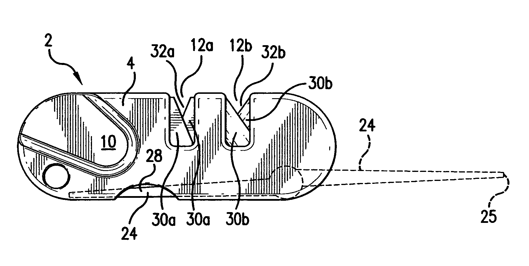
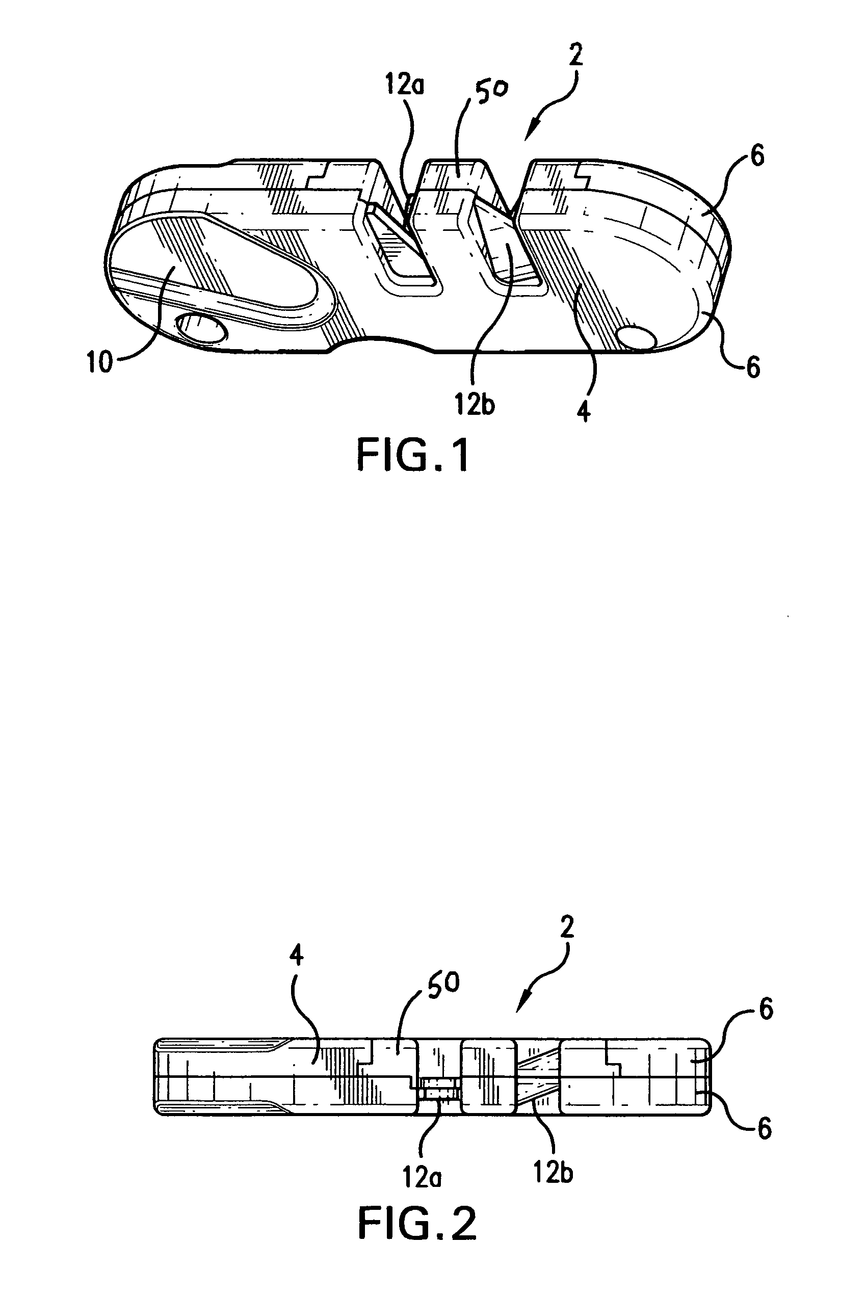
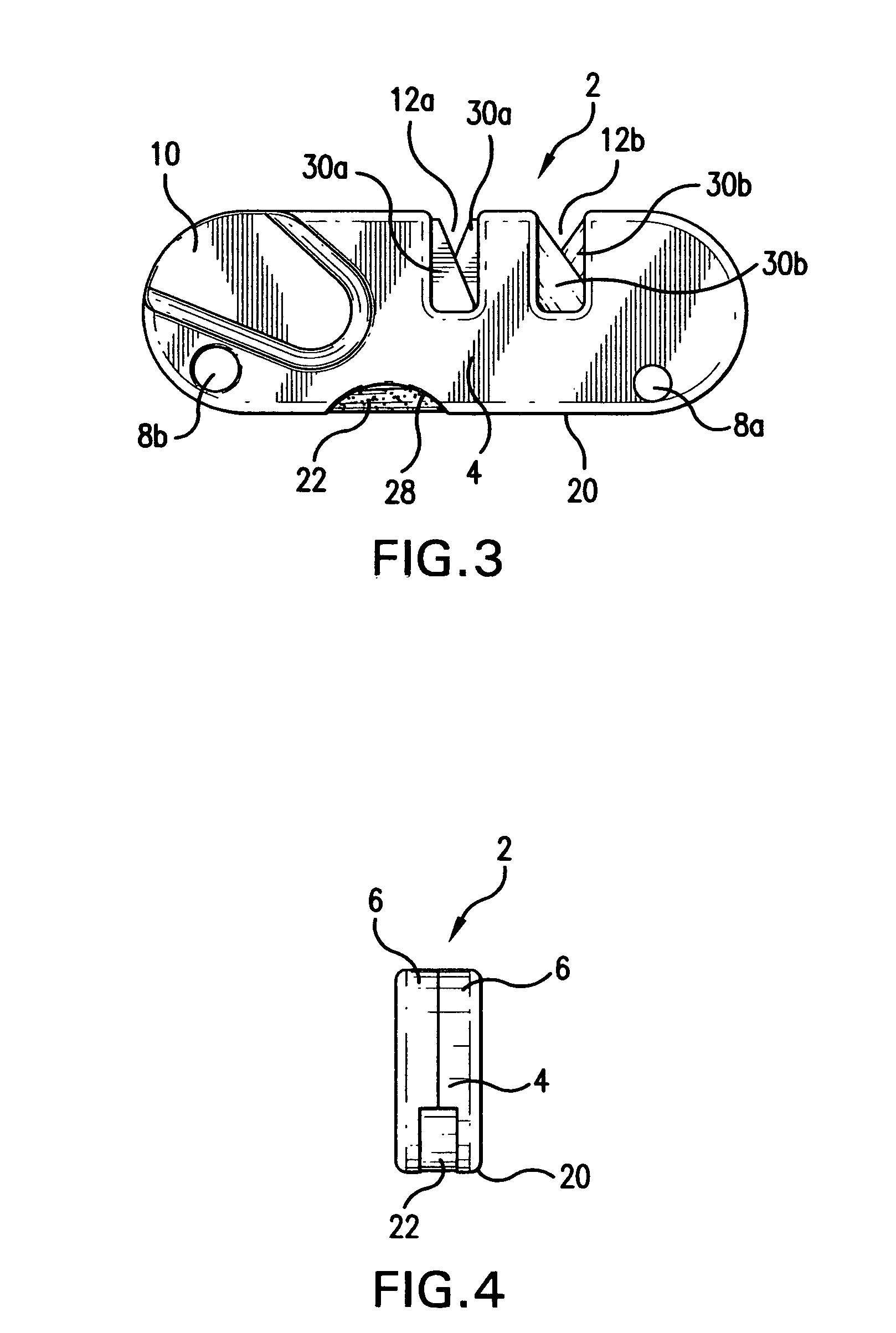
[0019]Referring now to FIGS. 1-6, there is illustrated the abrasive sharpener of the invention, generally designated by reference numeral 2. The pocket sharpener 2 has a body 4 formed by a pair of contacting body halves 6. The pair of halves 6 may be fabricated from a suitable plastic and are retained together to body 4 by an adhesive, welding, and the like and by a mechanical fastener received in hole 8a. A lanyard hole 8b is provided at the other end of housing 4. A recessed thumb depression 10 is formed on both of the body halves 6 at one end to form an area to allow the user to more firmly grip the sharpener during a sharpening task. A pair of lateral, side by side slots 12a, 12b, providing a pair of sharpening stations, are formed on the top of the body 4 to respectively receive overlapping offset flat blades having carbide abrasive edges and flat ceramic stones to be described later.

[0020]The bottom 20 of the sharpener body is open and forms a storage compartment 22 to receive...


PUM

PropertyMeasurementUnit
pre-set angleaaaaaaaaaa
abrasiveaaaaaaaaaa
widthaaaaaaaaaa

Abstract

A pocket abrasive sharpener having a housing formed with a pair of upper slots and a lower open compartment. A pair of abrasive ceramic stones is mounted in one of the slots to form a V-shaped sharpening slot. Each ceramic stone has at least one flat face to abut an adjacent reversed stone to form the V-shaped sharpening slot. The stone has an abrasive cutting edge formed with a radius for sharpening serrated edges and having abrasive surfaces on both sides of the radius. A pair of abrasive blades having V-shaped carbide cutting edges is mounted in the other of the slots to also form a V-shaped sharpening slot. A tapered abrasive rod is pivotally mounted on the housing and is moveable from the compartment to an extended position for sharpening knives and removing pins in certain military and civilian rifles.

Description

[0001]This application claims benefit of the priority date of provisional application, Ser. No. 60 / 879,832 filed Jan. 11, 2007.BACKGROUND OF THE INVENTION[0002]1. Field of the Invention[0003]This invention relates in general to abrasive sharpeners and, more particularly, to a hand held, abrasive sharpener.[0004]2. Summary of the Prior Art[0005]Numerous designs for portable abrasive sharpeners for serrated and straight edge knives and the like are known in the prior art. Some of the designs for hand held sharpeners have employed more than one sharpening capability. Such known designs, however, have not combined multiple abrasive sharpening elements in a small, hand held sharpener that can be readily transported and can produce highly effective sharpening results, whether to sharpen a straight edge or a serrated edge. In the past, opposed circular ceramic rods have been used in sharpeners. Because of the configuration the opposed abrasive surfaces are relatively spaced in a lateral di...

Claims


Application Information

Patent Timeline
Patent Type & Authority Patents(United States)
IPC IPC(8): B23F21/03
CPCB24B3/54B24D15/065B24D15/081
Inventor SMITH, RICHARD S.
Owner SMITHS CONSUMER PROD
Why Eureka
Try Eureka