Spur gear differential

a gear differential and gear gear technology, applied in the direction of differential gearings, belts/chains/gearrings, gearings, etc., can solve the problems of high cost of embodiments, high cost of subsequent work, and distortion inside components, and achieve simple and economical production, low installation space, and high torque transmission

Inactive Publication Date: 2012-07-17
SCHAEFFLER TECH AG & CO KG
View PDF12 Cites 25 Cited by
  • Summary
  • Abstract
  • Description
  • Claims
  • Application Information

AI Technical Summary

Benefits of technology

[0021]The connection between the housing sections becomes more rigid, so that the entire differential is more rigid and less susceptible against deformations and dislocations. Furthermore, less radial installation space for the drive wheel, or for its mounting at the housing, is possibly required, since the mounting was radially shifted—at least in part—between the planets.
[0025](4) The pot-shaped housing section and the disk-shaped section preferably consist of cold formed parts, e.g. drawn and punched parts of thin sheet metal, into which the receptacles for the planet gears and also the differential elements have been inserted. Such components can be produced cost-effectively.
[0035]Housing sections comprising the characteristics (5) through (11) are mutually supported through the pin guide, particularly peripherally, so that the screw connection is free from peripheral stresses caused by the torques (shear stress). The number of mounting elements, such as screw elements or rivets, can be reduced.
[0063]The tooth width for the engagement of the components of the differentials according to the invention engaged with each other is wider than that of the previous category-defining prior art with the same dimensions—since planet gears in pairs are nested one inside the other, and with the differential elements without additional axial gaps. Higher torques can be transmitted. The planet gears are not aligned at a separate planet carrier along the center in the differential, but on both sides inside the housing that functions as a planet carrier. Due to the two bearing positions—instead of one—the construction is more rigid and less susceptible against tipping, and thus less susceptible against the advantages caused by tipping.
[0064]The pairs of a planetary drive can be moved closer on top of one another on the periphery, since, for one, the stresses per planet are distributed to two bearing positions inside or at the housing, in each case, and, on the other hand, the housing design per se is already more stable than a disk-shaped sheet metal planet carrier aligned in the center. The installation space that needs to be available on the periphery between the individual bearing positions for supporting material is small. The need for installation space for a centrally aligned planet carrier is eliminated since the bearing is located inside the housing. The toothing can additionally be designed broader by this amount. This, in turn, allows reducing the contact radius, and one can resort to the more rigid embodiment, and thus against deformations, of less susceptible designs as those in FIG. 2, which depicts the planet gears engaging with the sun gears. The manufacture of the planetary drive is more cost-effective, since the expensive production of the ring gears is eliminated. Processing the interior of the internal toothing, for example, is costly.

Problems solved by technology

Under the most unfavorable conditions, the heat introduced by the welding may cause distortions inside the component and require costly subsequent work.
Such embodiments are very costly in terms of the quantity of the material for production and due to the time-consuming production.
However, the thin sheet metal can have a negative effect on the initially mentioned deformation behavior of the planet drive.
Accordingly, in turn it can also be disadvantageous if the contact radius is too big.
The use of more than three pairs and the transmission of high torques are difficult in terms of the available installation space in the arrangements of both embodiments in prior art pursuant to FIG. 1 of EP 0 918 177 A1.
A further difficulty for the light construction sheet metal differentials are the earlier described tolerance limits of the sheet metal planet carrier determined by deformations.
The differential becomes heavier and more expensive.
As a result of the more widely designed engagement the differentials require more installation space in lateral direction, thus axially, thus becoming heavier and more expensive overall.
Such a design requires additional axial installation space due to the axially longer planet gear.

Method used


Image

  • Spur gear differential
  • Spur gear differential
  • Spur gear differential

Examples


Embodiment Construction

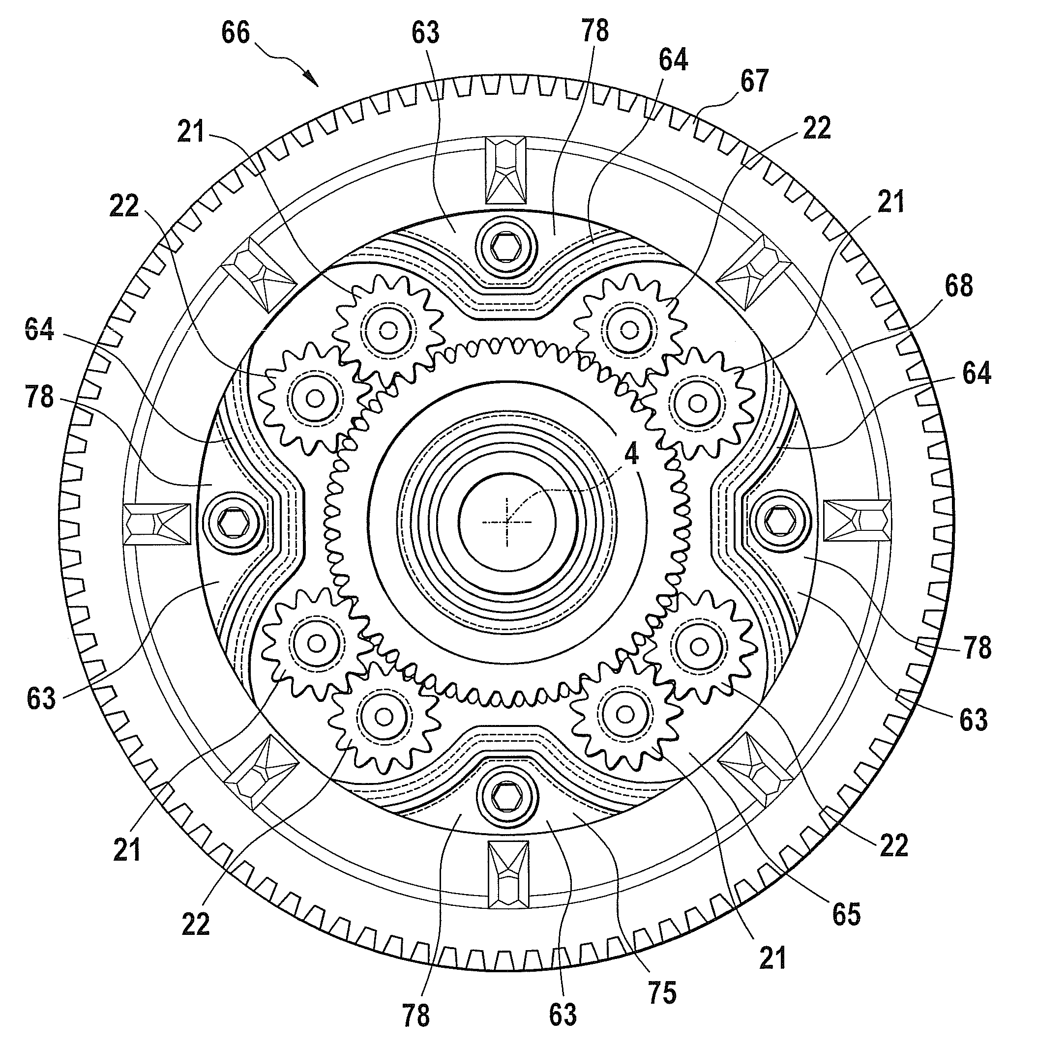
[0018]This task is solved with a spur gear differential that uses on its periphery installation space for the connection of the housing sections between the individual pairs of the planet gears.

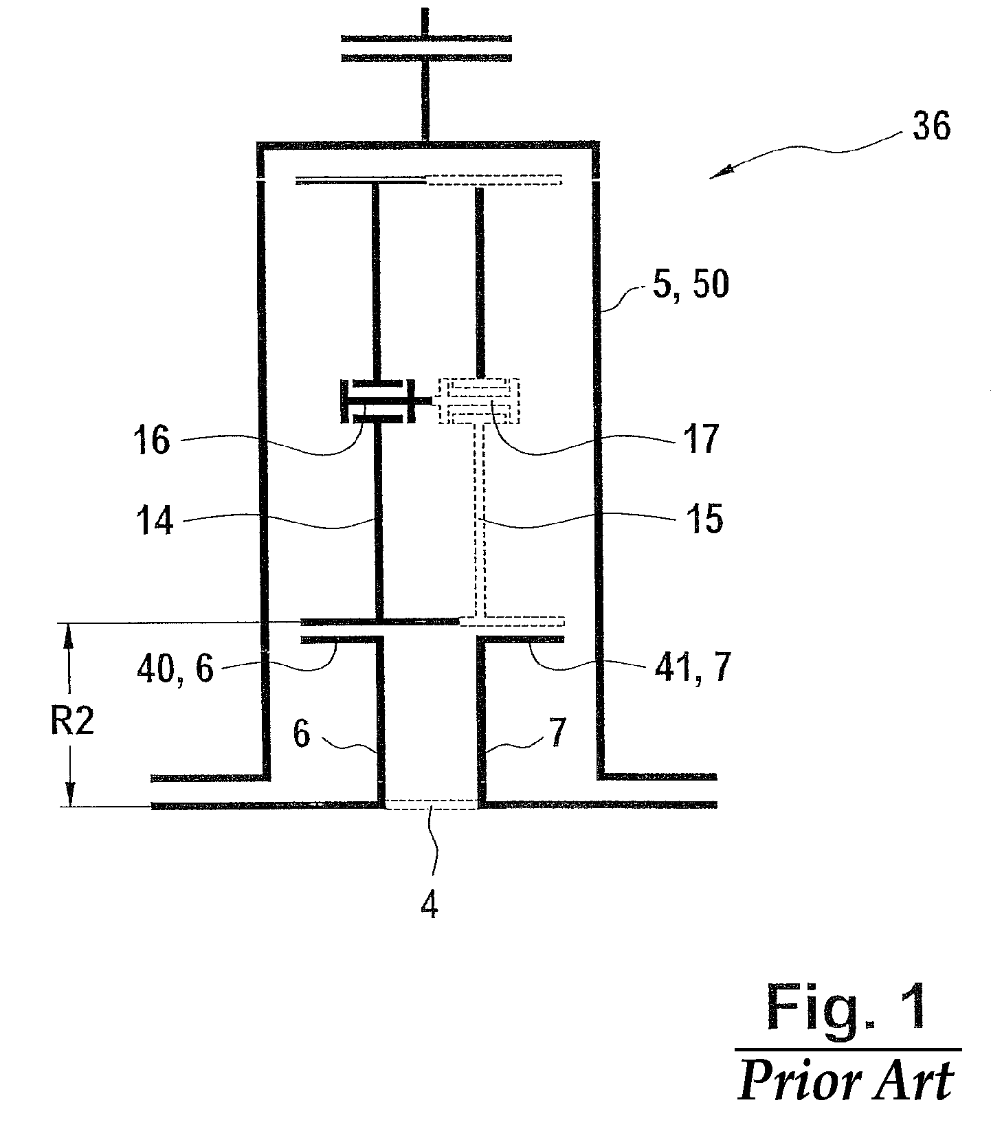
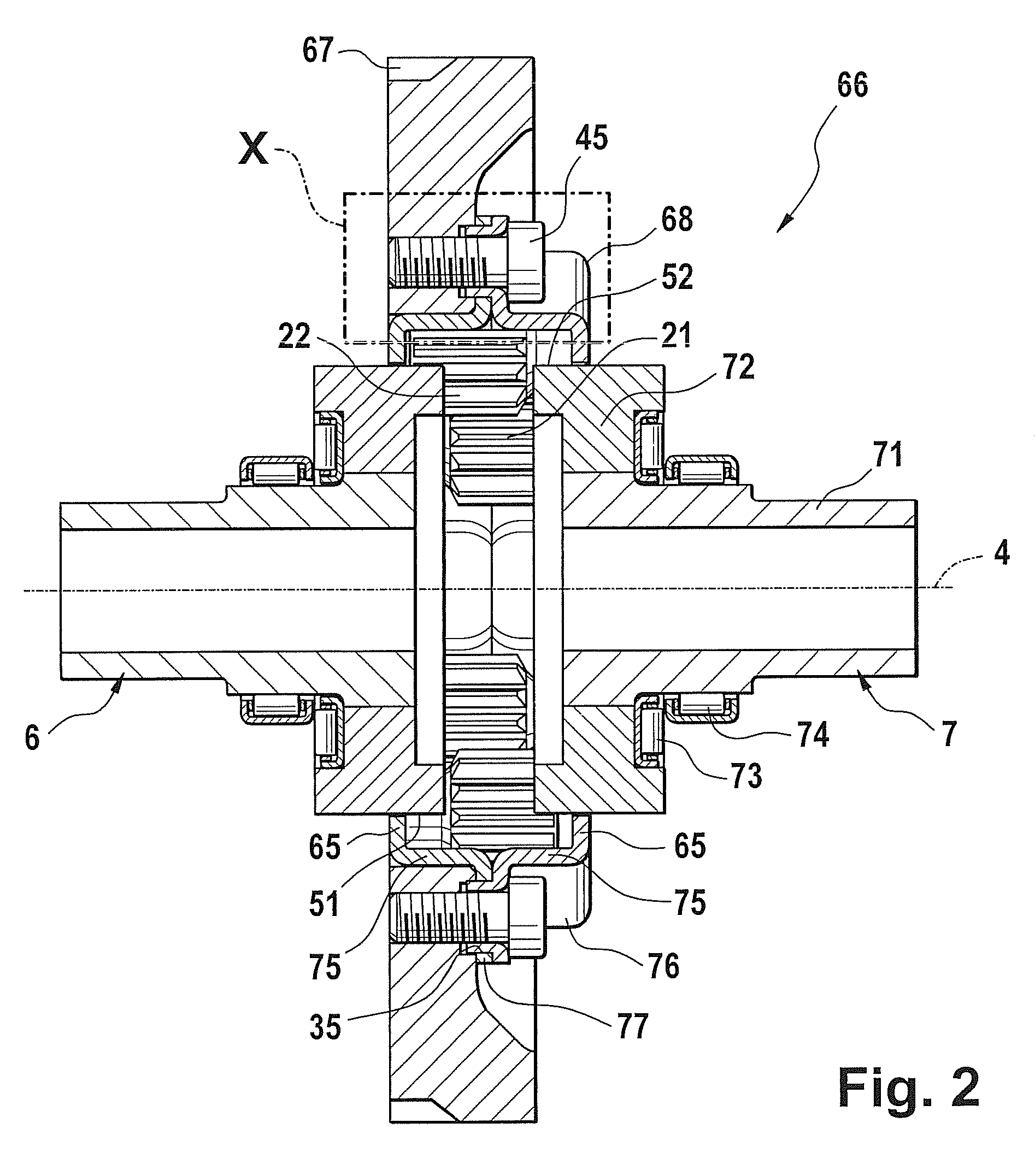
[0019]The spur gear differential is comprised of an at least two-part housing embodied as a sum wheel that can rotate around a longitudinal rotational axis, and at least three planet gears that are disposed on the periphery at a distance in relation to each other around the rotational axis, and a drive wheel at the housing. The housing is formed from at least two housing sections that are fixed to each other. One of the housing sections may be embodied as a pot or a bowl, and the other one as a lid. Preferably, however, both housing sections are embodied like a pot and identical parts.

[0020]The wall of the pot that extends around the rotational axis comprises at least two wall sections curved towards the inside in a radial manner, i.e. the wall is drawn or curved towards the inside in these a...


PUM


Abstract

The invention relates to a spur gear differential (66) comprising a housing (68) that is embodied as a sum wheel (50) and that rotates around a longitudinal rotational axis (4), at least three planet gears (21, 22) disposed on the periphery at a distance in relation to each other around the rotational axis (4), and a drive wheel (67) at the housing (68), withthe housing (68) comprised of at least two housing sections (75) fixed to each other,each of the planet gears (21, 22) mounted longitudinally on both sides in the housing sections (75),at least one of the housing sections (75) formed in the shape of a pot, with the housing section (75) formed from a pot (76) having a base (65) arranged on the front side of the housing, a wall starting from the base (65) and extending around the rotational axis (4).

Description

FIELD OF THE INVENTION[0001]EP 0 918 177 A1 shows spur gear differentials of the category-defining prior art. For better understanding, the differential of the category-defining prior art is schematically represented below in FIG. 1 in a simplified manner and described below. The principle corresponds to an embodiment of the differentials described in EP 0 918 100 770 A1, which will be explained in greater detail in the following.[0002]The planet carrier, or the planet carrier's housing, of the category-defining type is the differential's so-called sum wheel. The sum wheel represents the element that has the maximum torque, in each case. The input shafts are coupled to the driven gears in a rotationally fixed manner, representing the so-called difference shafts. Said difference shafts each forward a difference of the torques introduced into the differential, for example to the driven wheel vehicle. In the category-defining prior art described hereinabove and below the planet carrier...

Claims


Application Information

Patent Timeline
Patent Type & Authority Patents(United States)
IPC IPC(8): F16H48/10F16H48/11
CPCF16H48/10F16H48/11F16H48/40F16H2048/106F16H2048/382
Inventor BIERMANN, THORSTENJURJANZ, RAMON
Owner SCHAEFFLER TECH AG & CO KG
Why Eureka
Try Eureka