Magnetic coupling type isolator
a technology of isolators and magnetic couplings, which is applied in the direction of transformers/inductance coils/windings/connections, instruments, etc., can solve the problem of not being able to obtain a sufficient tolerance to external magnetic fields or ems, and achieve the effect of sufficient toleran
- Summary
- Abstract
- Description
- Claims
- Application Information
AI Technical Summary
Benefits of technology
Problems solved by technology
Method used
Image
Examples
embodiment 1
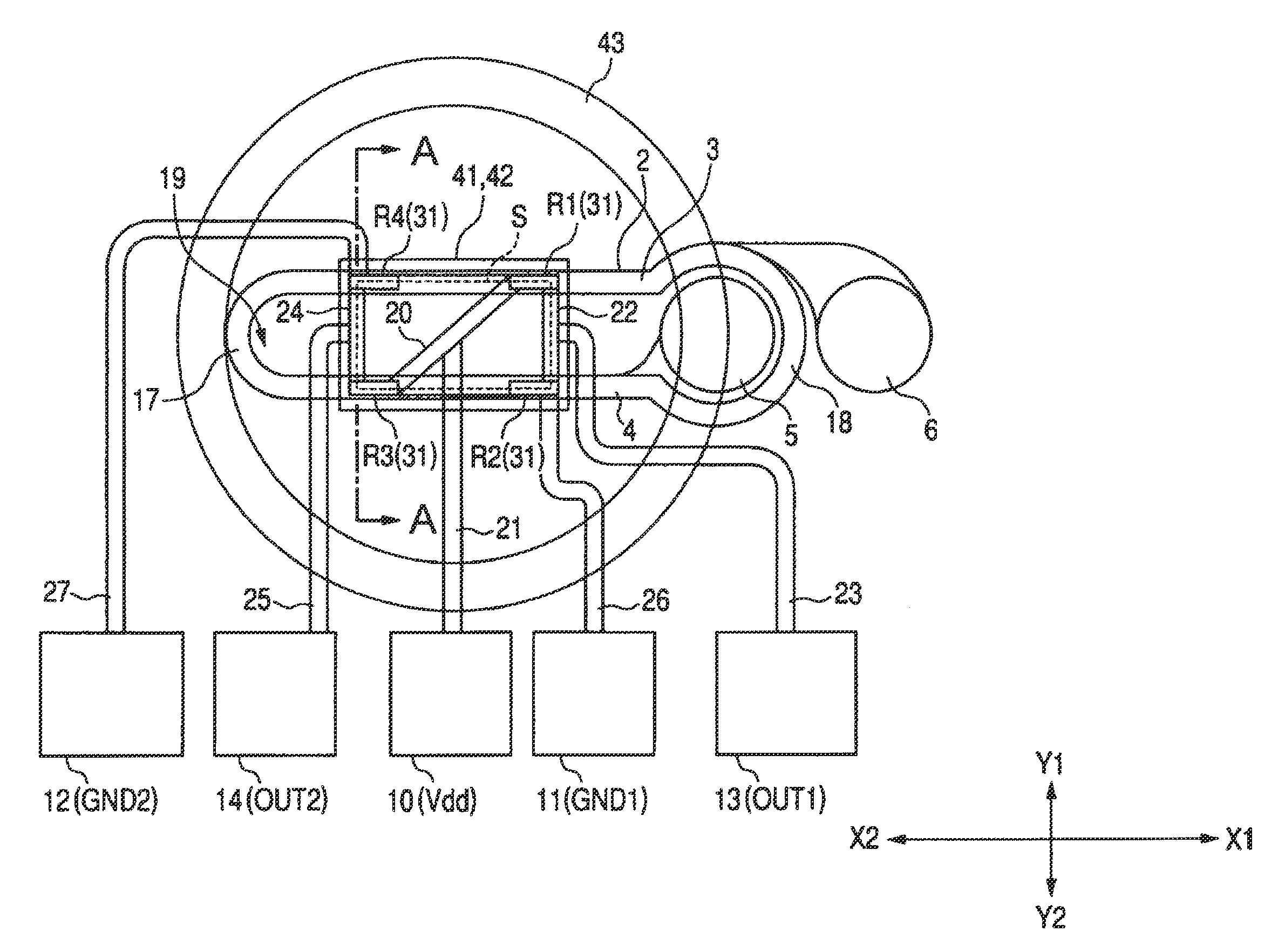
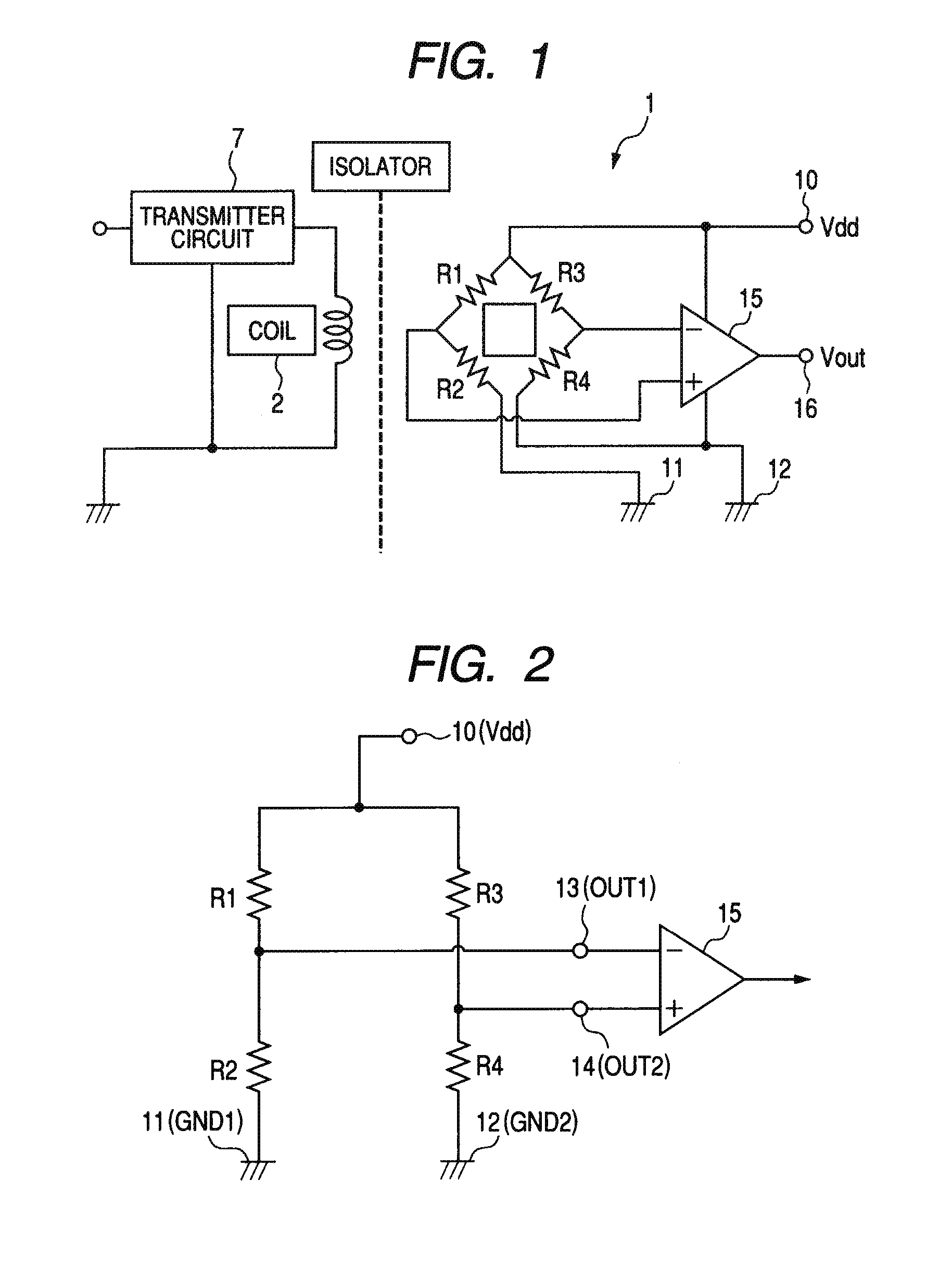
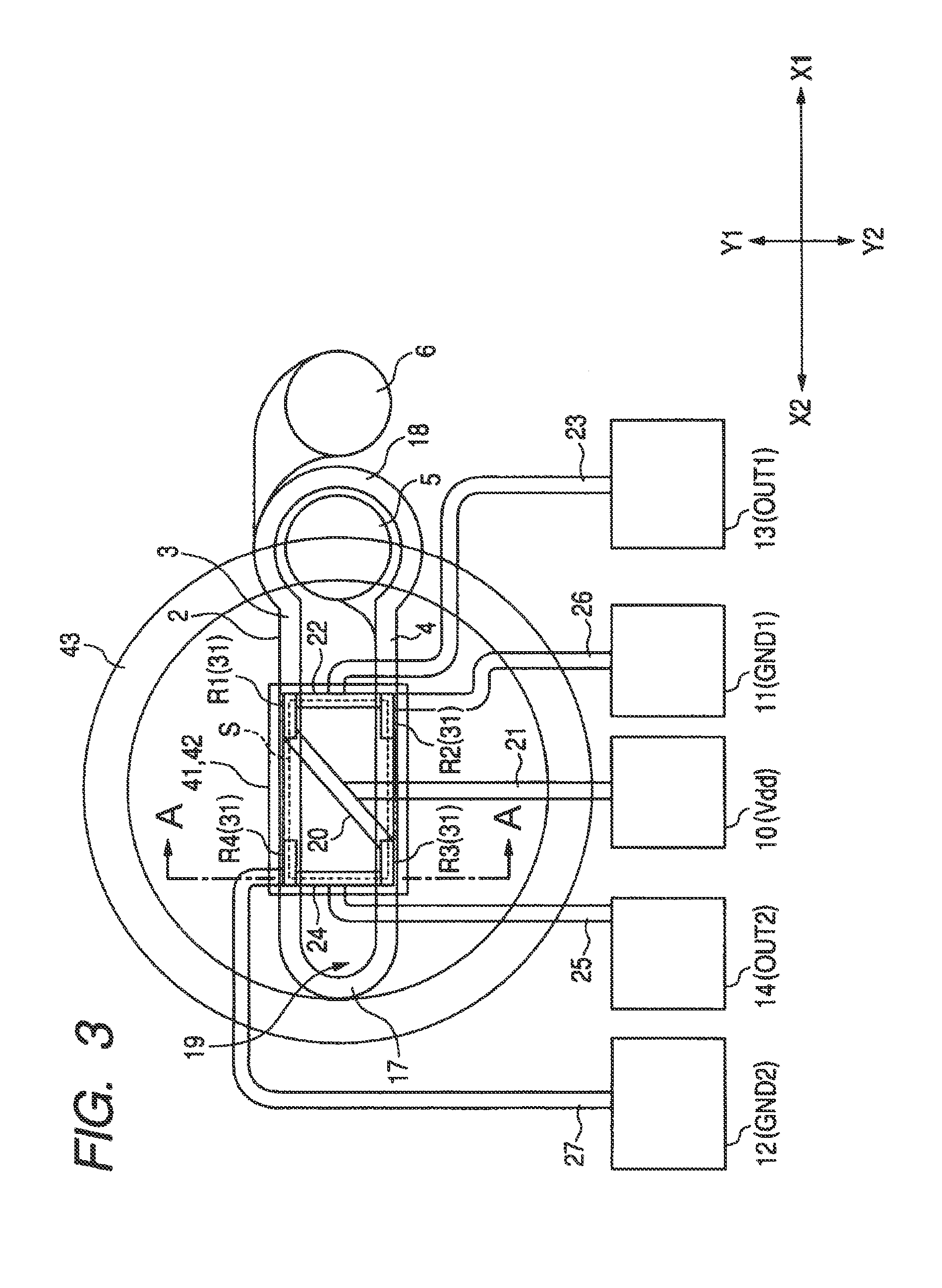
[0039]FIG. 1 is a circuit diagram illustrating an entire configuration of a magnetic coupling type isolator (or magnetic coupler) according to an embodiment of the invention. FIG. 2 is a circuit diagram illustrating a bridge circuit including magnetoresistive elements R1 to R4. FIG. 3 is a partial plan diagram illustrating a magnetic coupling type isolator according to an embodiment of the invention. FIG. 4 is a partially cross-sectional diagram viewed from an arrow direction and cut away in a thickness direction along a line A-A of FIG. 3. In addition, while the insulation layer is not shown, and only the inner and outer edges of the coil 2 are shown in FIG. 3, the magnetoresistive elements R1 to R4 underlying the coil 2 are shown by transparency.
[0040]As shown in FIG. 1, the magnetic coupling type isolator 1 includes a coil 2 as a magnetic field generator for generating an external magnetic field by the input signal and magnetoresistive elements R1 to R4 for detecting the external...
embodiment 2
[0085]In this embodiment of the invention, a case where the width of the middle shield film 43 is specified will be described. In this case, the middle shield film 43 has a ring shape as seen in a top plan view, and the width and the shield effect thereof were examined. In other words, in the configuration having the upper, lower, and middle shield films 41, 42, and 43 provided around the magnetoresistive elements R1 to R4, a percentage of the magnetic field received by the magnetoresistive element was examined in a case where an external magnetic field of 20 mT is applied to the magnetic coupling type isolator in a direction of the arrow of FIG. 5 (i.e., the horizontal direction with respect to the middle shield film 43) by changing the width of the middle shield film 43 as seen in a top plan view. The result is shown in FIG. 8. For a comparison purpose, another magnetic coupling type isolator having the same configuration as that of FIG. 5 except that the upper and lower shield fi...
embodiment 3
[0087]In this embodiment of the invention, a case where the shapes of the upper and / or lower shield film are specified will be described. As shown in FIG. 9A, it is more preferable that the upper and / or lower shield films 41 and / or 42 have a shape 41a or 42a having a curvature R at the corner portions in comparison with a rectangular shape in terms of the shield effect. In other words, it is preferable that the upper and / or lower shield films 41 and 42 have a circular or elliptical shape as seen in a top plan view, or an n-polygonal shape (n=4 to ∞) having a curvature at the corner portions as seen in a top plan view.
[0088]In comparison with the shape having the corner portions shown in FIG. 9B, the shape having the curvature in the corner portions shown in FIG. 9C is more advantageous to increase the magnetic permeability and improve the shield effect because the volume of the magnetic domain generated within the shield film can be reduced, and the magnetic domain displacement caus...
PUM
| Property | Measurement | Unit |
|---|---|---|
| width | aaaaa | aaaaa |
| thickness | aaaaa | aaaaa |
| external magnetic field | aaaaa | aaaaa |
Abstract
Description
Claims
Application Information
 - R&D
- Intellectual Property
- Life Sciences
- Materials
- Tech Scout
- Unparalleled Data Quality
- Higher Quality Content
- 60% Fewer Hallucinations
Browse by: Latest US Patents, China's latest patents, Technical Efficacy Thesaurus, Application Domain, Technology Topic, Popular Technical Reports.
© 2025 PatSnap. All rights reserved.Legal|Privacy policy|Modern Slavery Act Transparency Statement|Sitemap|About US| Contact US: help@patsnap.com


