Device for distributing charge material into a shaft furnace

a shaft furnace and charge material technology, applied in the direction of gearing, furnaces, instruments, etc., can solve the problems of high manufacturing precision, high cost, and high risk of premature wear, and achieve the effect of less stringent requirements for manufacturing precision and increasing the risk of premature wear

Active Publication Date: 2014-12-30
PAUL WURTH SA
View PDF16 Cites 4 Cited by
  • Summary
  • Abstract
  • Description
  • Claims
  • Application Information

AI Technical Summary

Benefits of technology

[0006]In view of the foregoing, the invention provides a device for distributing charge material into a shaft furnace with a differential driving system the design of which renders requirements concerning manufacturing precision less stringent without increasing the risks of premature wear of the driving system components, in particular of the differential gear.
[0013]The two separate gear casings forming independent fixed mounting frameworks enabling independent positioning and parallelism between two groups of gear components: namely those required for the differential gear, i.e. differential torque transmission from the main drive to the adjustment rotor, and those required for direct torque transmission from the main rotation drive to the suspension rotor. Accordingly, the second casing need only contain those shafts, and thus properly locate and orientate the minimum axes necessary by definition for the differential gear plus a single axis for connecting the shaft arrangement to the differential gear, thus reducing potential sources of misalignment or positioning mismatch that could affect durability of the differential. The proposed design excludes that any minor anti-parallelism or positioning inaccuracy between the first and second output shafts (on the side of the rotors) and between the first and second input shafts (on the side of the drives) respectively, could increase wear-off. As will be appreciated, the proposed configuration excludes in particular that either such anti-parallelism or positioning inaccuracy could reduce the service-life of the differential.
[0016]Whenever placement and orientation of the separate casings is non-critical, the connecting shafts between the casings can be substantially aligned and, in this case, the compensating coupling may be a cost-effective Oldham coupling or a jaw coupling, which provides sufficient tolerance. When further flexibility concerning placement and orientation of the separate casings is desired however, the compensating coupling is preferably a homokinetic universal joint arrangement, in particular a dual Cardan shaft comprising two Cardan joints ensuring homokinetic transmission. More preferably, a dual Cardan shaft with length compensation, e.g. a dual Cardan shaft length-extensible intermediate shaft, is used to provide further positioning tolerance. To facilitate construction and to avoid additional requirements concerning installation of the dual Cadan shaft, each of the two Cardan joints is preferably a centered double Cardan joint.

Problems solved by technology

Therefore, manufacture of the drive unit, especially due to high precision machining of the casing 1, tends to be relatively expensive in order to avoid any risk of premature wear, especially of the planetary differential mechanism 8, which is itself a heavy-duty and thus relatively costly component.
Typical high-precision drilling operations as well as other high-precision manufacturing practices can however still introduce minor inaccuracies as regards the positioning and orientation of the bearings that define the various axes A2, A3, A4, A5 and A7 so that wear cannot be minimized in cost-optimal manner.
Moreover, experience has shown that failure of the planetary differential mechanism 8, even though being rare is nevertheless one of the major sources of outage of the driving system.

Method used


Image

  • Device for distributing charge material into a shaft furnace
  • Device for distributing charge material into a shaft furnace
  • Device for distributing charge material into a shaft furnace

Examples


Embodiment Construction

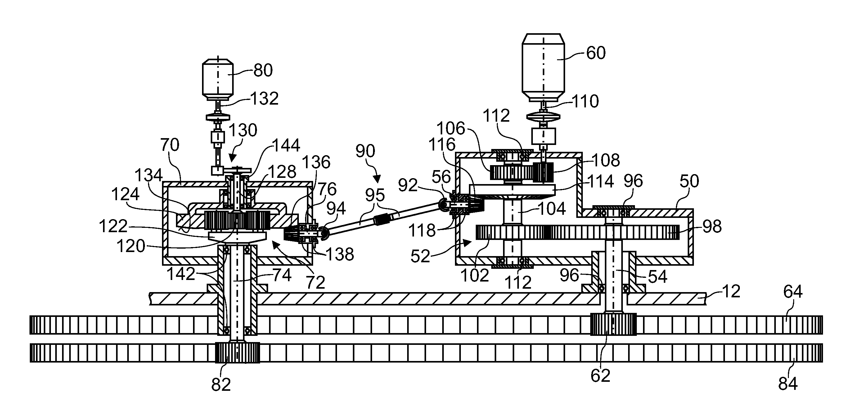
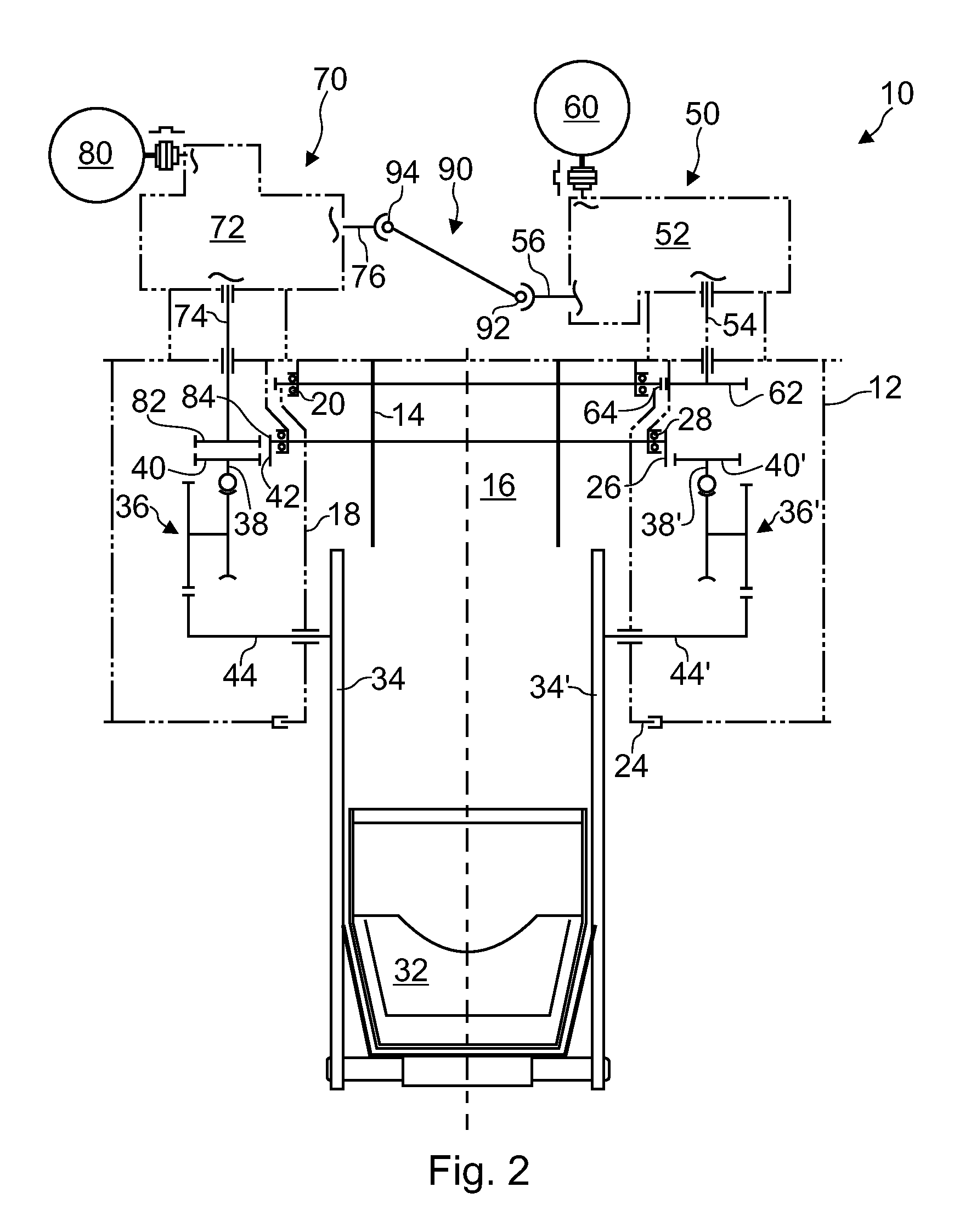
[0027]FIG. 2 illustrates a device 10 for distributing bulk charge material (“burden”) into a shaft furnace, especially onto the stockline of a blast furnace. The device 10 is designed to be part of a charging installation, which is not shown in its entirety. It comprises a main housing 12 to be arranged on the furnace throat and which includes a fixed feeding spout 14 that defines a vertical feeding channel 16. A suspension rotor 18 is suspended inside the main housing 12 by means of a first large-diameter annular roller bearing 20 to be rotatable about a substantially vertical rotation axis. The suspension rotor 18 comprises a generally cylindrical body provided at its lower in with a disk-shaped horizontal protection flange 24, which forms a screen between the interior of the main housing 12 and the interior of the furnace. A second rotor, hereinafter called adjustment rotor 26, surrounds the suspension rotor 18 and is suspended inside the main housing 12 by means of a second larg...


PUM

PropertyMeasurementUnit
speedaaaaaaaaaa
flexibleaaaaaaaaaa
lengthaaaaaaaaaa

Abstract

A shaft furnace charge material distribution device includes a main housing, a distribution chute, a suspension rotor and an adjustment rotor, which are rotatable about a vertical axis. The chute is suspended to the suspension rotor to rotate therewith for circumferential distribution of charge material and is adjustable in orientation for radial distribution of charge material. A differential gear interconnects the suspension rotor and adjustment rotor and is configured to transmit to the adjustment rotor the same speed of rotation that is imparted to the suspension rotor by a main rotation drive unless an adjustment drive imparts differential rotation to the adjustment rotor. The device includes two gear casings arranged on the main housing and a shaft arrangement. The first gear encloses a gear mechanism connecting the main rotation drive to one output shaft. The second gear casing encloses the differential gear connecting the adjustment drive to another output shaft.

Description

TECHNICAL FIELD[0001]The present invention generally relates to a charging installation for a shaft furnace and in particular to a distribution device equipped with a chute for circumferential and radial distribution of charge material into the furnace. More specifically, the invention relates to the driving system for operating the chute in this type of device.BRIEF DISCUSSION OF RELATED ART[0002]A device for distributing charge material into a shaft furnace is known from U.S. Pat. No. 3,693,812. The device according to U.S. Pat. No. 3,693,812 has a suspension rotor and a chute adjustment rotor that are supported in a main housing so as to be rotatable about a substantially vertical rotation axis, which typically corresponds to the furnace axis. In typical manner, the chute is suspended to the suspension rotor so that it rotates with the latter for circumferential distribution of charge material. Furthermore, in the device according to U.S. Pat. No. 3,693,812, the chute is suspende...

Claims


Application Information

Patent Timeline
Patent Type & Authority Patents(United States)
IPC IPC(8): F27D3/10F27B1/24F16H37/08C21B7/20F27B1/20
CPCF27B1/20F16H37/0806F27D3/10C21B7/20C21B7/205
Inventor THILLEN, GUYLONARDI, EMILEHAUSEMER, LIONELTHIX, CHRISTIAN BENOIT
Owner PAUL WURTH SA
Why Eureka
Try Eureka