
Temperature sensor of a CPU and PWM controller thereof

a temperature sensor and controller technology, applied in the field of power supply circuits, can solve problems such as cpu generating an excess of hea

Inactive Publication Date: 2012-07-17
GOLD CHARM LTD
View PDF7 Cites 0 Cited by
  • Summary
  • Abstract
  • Description
  • Claims
  • Application Information

AI Technical Summary

Benefits of technology

"The present patent is about a power supply circuit for a CPU (central processing unit) that provides stable power to the CPU. The circuit uses a PWM controller to generate three pulse signals that control a corresponding switch to provide a multiphase power source to the CPU. The pulse signals are generated to have different phases, such as phase 1, phase 2, and phase 3, and each phase controls a different switch to ensure stable power to the CPU. However, the prior art circuit has drawbacks, such as interfered pulse signals and unstable power sources, which cause instability and excess heat generation in the CPU. The present disclosure addresses these drawbacks by incorporating a temperature feedback circuit that detects the current temperature of the CPU and adjusts the pulse signals accordingly to maintain stable power to the CPU. The technical effect of the present patent is to provide a more stable and efficient power supply circuit for the CPU."

Problems solved by technology

However, the pulse signals are easily interfered with and generate disorder jitters which cause the power provided to the CPU to be unstable and result in the CPU generating a an excess of heat.

Method used


Image

  • Temperature sensor of a CPU and PWM controller thereof
  • Temperature sensor of a CPU and PWM controller thereof
  • Temperature sensor of a CPU and PWM controller thereof

Examples


Embodiment Construction

[0011]The disclosure is illustrated by way of example and not by way of limitation in the figures of the accompanying drawings in which like references indicate similar elements. It should be noted that references to “an” or “one” embodiment in this disclosure are not necessarily to the same embodiment, and such references mean at least one.

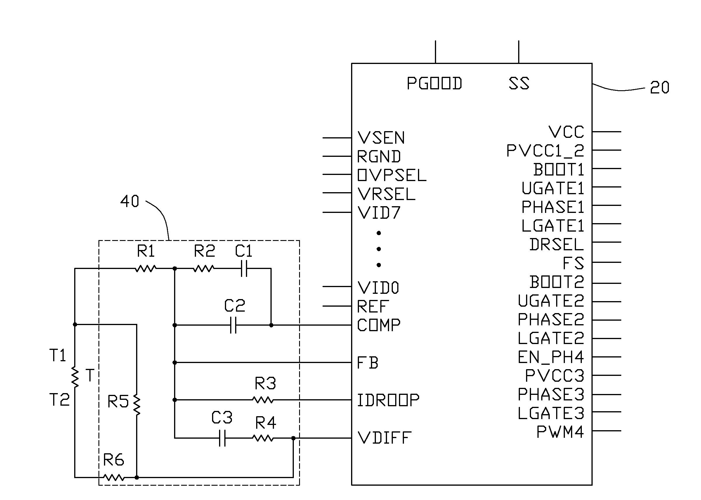
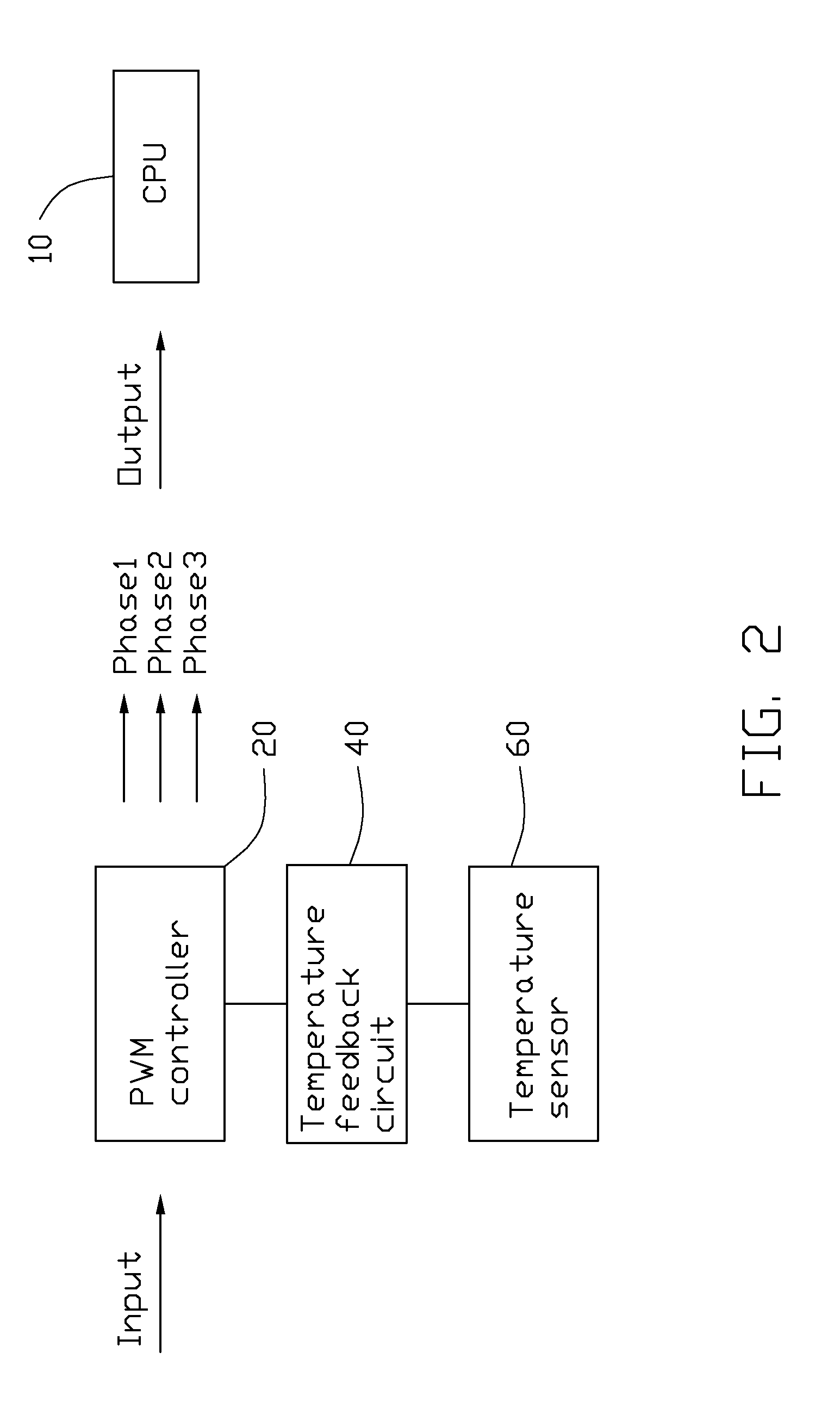
[0012]Referring to FIG. 2, a power supply circuit in an embodiment for providing power to a CPU 10, includes a PWM controller 20, a temperature feedback circuit 40, and a temperature sensor 60. The temperature feedback circuit 40 is connected to the PWM controller 20. The temperature sensor 60 is connected to the temperature feedback circuit 40. The temperature sensor 60 is capable of detecting a current temperature of the CPU 10, and generating a current temperature signal that is sent to the temperature feedback circuit 40.

[0013]Referring to FIG. 3, the PWM controller 20 includes a plurality of pins, such as pin COMP, pin FB, pin IDROOP, pin VD...


PUM

PropertyMeasurementUnit
temperatureaaaaaaaaaa
temperature coefficientaaaaaaaaaa
voltageaaaaaaaaaa

Abstract

A power supply circuit includes a PWM controller, which is capable of providing pulse signals to the CPU, a temperature feedback circuit coupled to the PWM controller, and a temperature sensor. The temperature sensor is coupled to the temperature feedback circuit, the temperature sensor is located adjacent the CPU, and capable of detects a temperature of the CPU. The PWM controller is capable of adjusting the pulse signals to maintain the pulse signals stably when the temperature sensor detects the temperature of the CPU rising.

Description

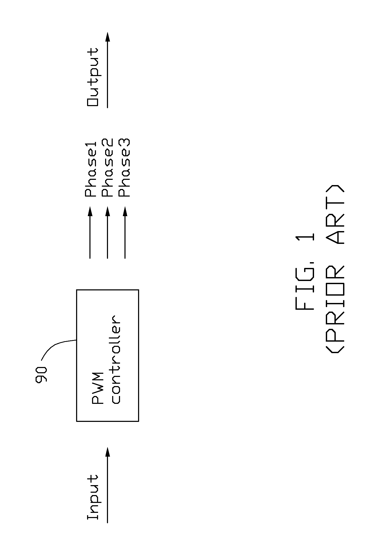
BACKGROUND[0001]1. Technical Field[0002]The present disclosure relates to power supply circuits, and particularly to a power supply circuit for providing power to a CPU (central processing unit).[0003]2. Description of Related Art[0004]With the rapid development of personal computers, development of high performance components for computers have brought about a corresponding increase in power use. A CPU has a crucial effect on the stability of the computer. A power supply circuit is specially designed for providing power to the CPU.[0005]Referring to FIG. 1, a typical power supply circuit for a CPU, according to the prior art, includes a PWM (pulse-width modulation) controller 90 which provides three pulse signals. The three pulse signals have different phases, such as phase 1, phase 2, and phase 3. Each of the three pulse signals controls a corresponding switch on or off on different time to provide multiphase power source to the CPU. The multiphase power source usually generates l...

Claims


Application Information

Patent Timeline
Patent Type & Authority Patents(United States)
IPC IPC(8): H01L35/00G06F1/32G01K7/00G05F1/10H03K17/14H10N10/00
CPCG06F1/206G06F1/26G06F1/32
Inventor HU, KE-YOU
Owner GOLD CHARM LTD
Learn More