Eureka AIR delivers breakthrough ideas for toughest innovation challenges, trusted by R&D personnel around the world.

Joint carrier synchronization and channel equalization method for OFDM systems

a carrier and channel equalization technology, applied in the field of carrier synchronization and channel equalization methods, can solve the problems of insufficient accuracy, further degrading system performance, and inability to accurately estimate frequency, so as to increase the system performance of an ofdm system, minimize error power, and maximize the effect of sub-channel snr concurrently

Inactive Publication Date: 2012-07-17
NAT CENT UNIV
View PDF3 Cites 2 Cited by
  • Summary
  • Abstract
  • Description
  • Claims
  • Application Information

AI Technical Summary

Benefits of technology

[0019]A major objective of the present invention is to provide a joint carrier synchronization and channel equalization method for OFDM systems, wherein, a single cost function mechanism is employed to minimize the error power on each sub-channel and to further maximize the sub-channel SNR concurrently. The joint method is used to obtain the phase error and the gain error of each sub-channel signal simultaneously, hereby to solve the problems caused by the CFO and the channel distortion, further to increase the system performance of an OFDM system, and also to minimize Bit-Error-Rate (BER) for the OFDM system.

Problems solved by technology

However, such a frequency estimation mechanism is not a perfect process.
Therefore, such a phenomenon will result in the constellation rotation on each sub-channel in an OFDM system, hereby further degrading the system performance.
However, this method is not very accurate.
The residual CFO will destroy the accuracy of the channel estimation on each sub-channel since the residual CFO has not been fully removed.
Furthermore, the mutual interference will occur between the carrier frequency synchronization and the channel equalization to degrade the system performance, namely increase Bit Error Rate (BER) for an OFDM system.
As such, presently, the performance of the carrier frequency synchronization and the channel equalization techniques of the prior art is still not quite satisfactory, and it has much room for improvements.

Method used


Image

  • Joint carrier synchronization and channel equalization method for OFDM systems
  • Joint carrier synchronization and channel equalization method for OFDM systems
  • Joint carrier synchronization and channel equalization method for OFDM systems

Examples


Embodiment Construction

[0030]The purpose, construction, features, functions and advantages of the present invention can be appreciated and understood more thoroughly through the following detailed descriptions with reference to the attached drawings.

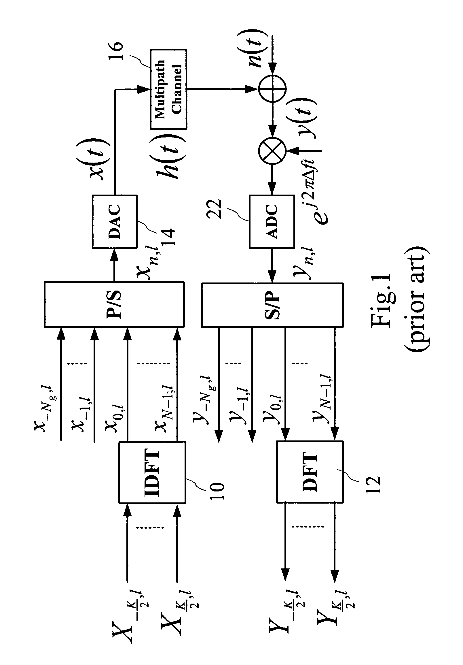
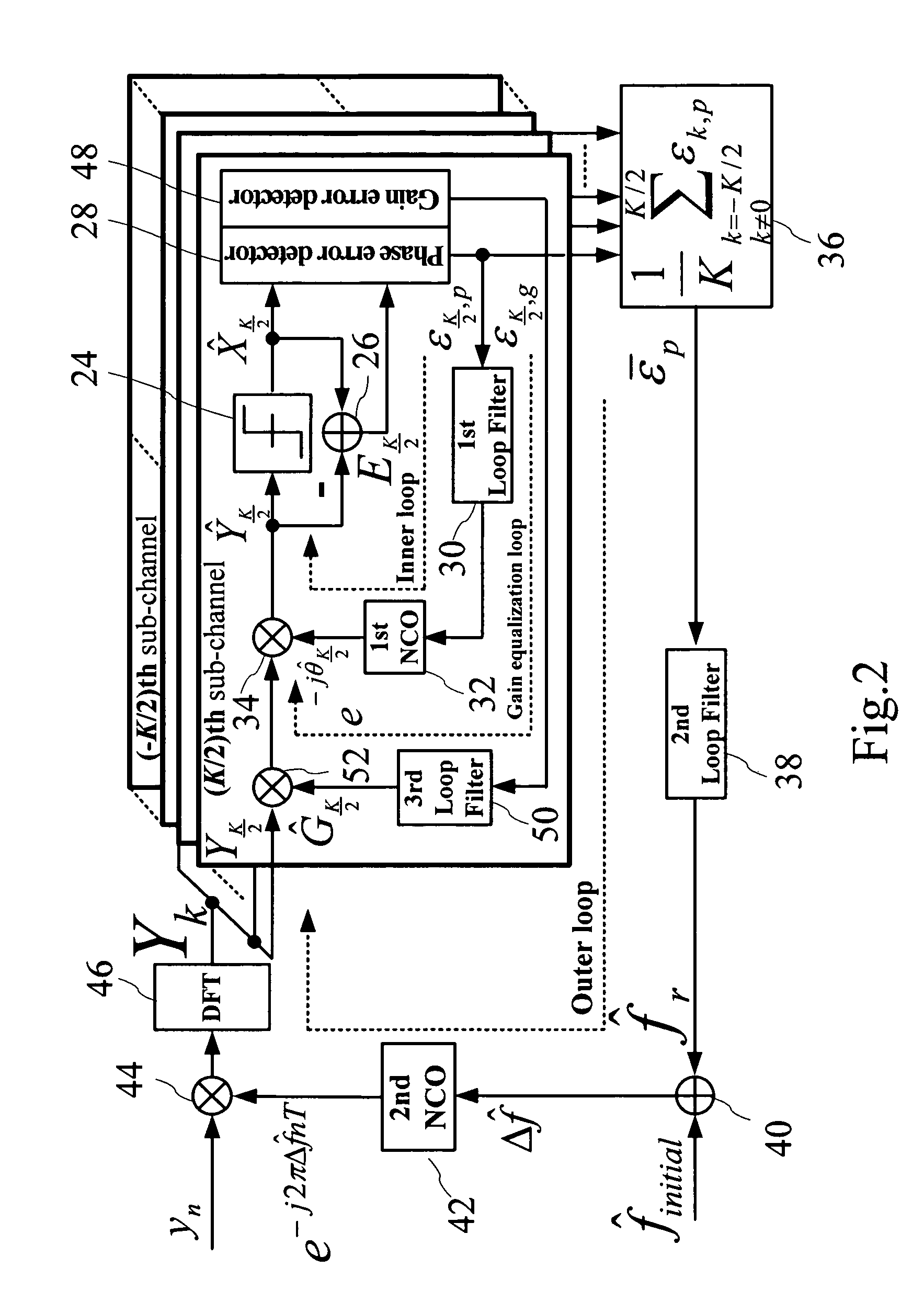
[0031]Firstly, referring to FIG. 1 for a device configuration of a baseband equivalent model for orthogonal frequency division multiplexer (OFDM) according to the prior arts, wherein, it is found that the carrier frequency offset (CFO) Δf causes a linear increment of phase offset in the time domain signals. In order to solve this problem of the prior art, the present invention proposes a joint carrier synchronization and channel equalization device, that is suitable for use in a receiver of an OFDM system, as shown in FIG. 2 for a schematic diagram of a device according to a first embodiment of the present invention.

[0032]In the following descriptions referring to FIG. 2. As shown in FIG. 2, a joint carrier synchronization and channel equalization device mainl...


PUM


Abstract

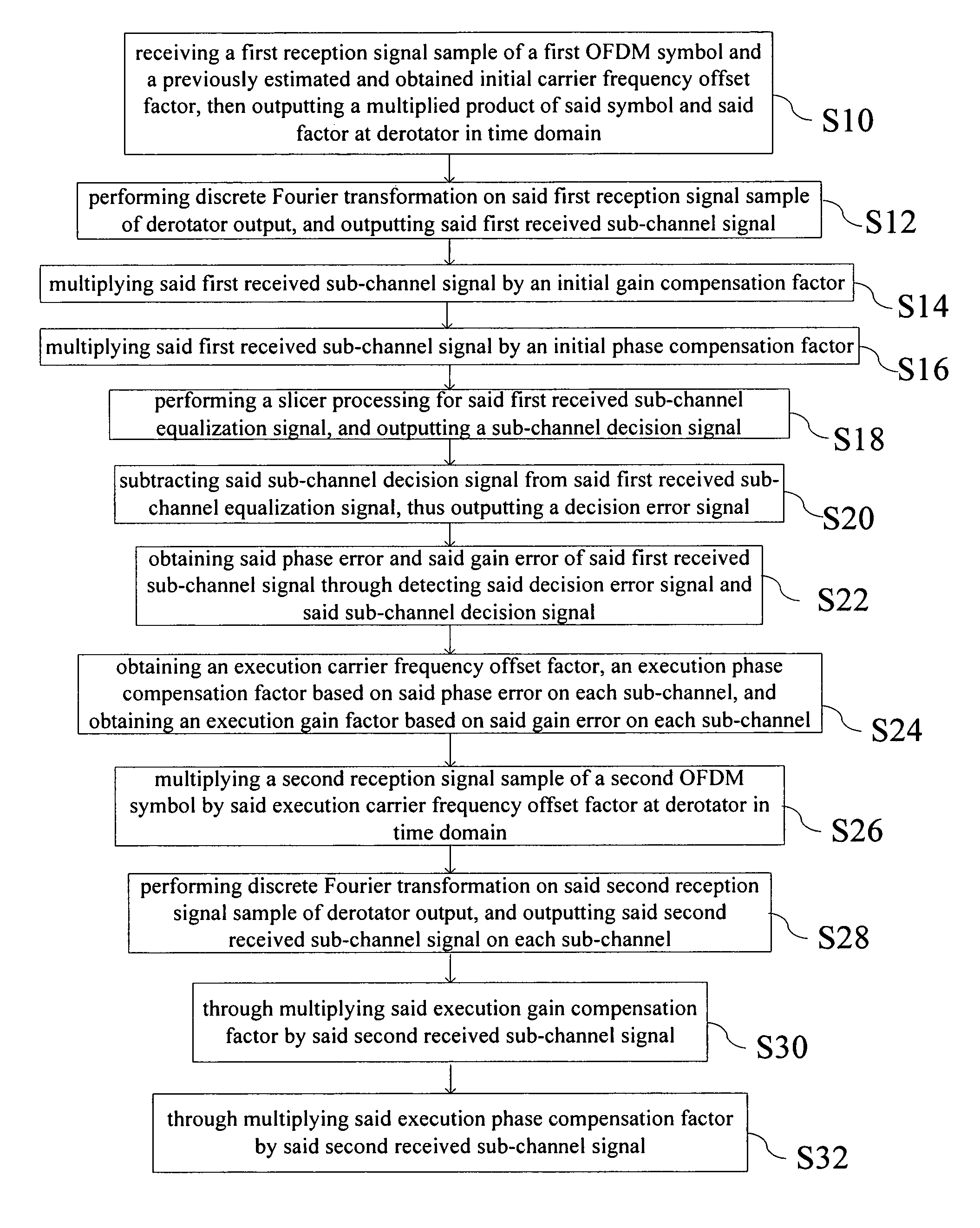
A joint carrier synchronization and channel equalization method for OFDM systems, that is suitable for use in a receiver of said orthogonal frequency division multiplexer (OFDM) systems, comprising the following steps: firstly, receiving a reception signal sample of an OFDM symbol, and obtaining simultaneously a phase error and a gain error on each sub-channel in a frequency domain, through outputting a sub-channel signal on each said sub-channel in said frequency domain; next, obtaining an execution carrier frequency offset factor, an execution phase compensation factor, and an execution gain compensation factor based on said phase error and said gain error; and finally, eliminating a phase offset of said reception signal sample of a next symbol in a time domain based on said factors, and compensating a magnitude distortion and a phase distortion on each said sub-channel in said frequency domain for said reception signal of said next symbol.

Description

BACKGROUND OF THE INVENTION[0001]1. Field of the Invention[0002]The present invention relates to a carrier synchronization and channel equalization method, and in particular to a joint carrier synchronization and channel equalization method for OFDM systems.[0003]2. The Prior Arts[0004]In the prior art, a device configuration of a baseband equivalent model for Orthogonal Frequency Division Multiplexer (OFDM) is shown in FIG. 1. Wherein, an inverse discrete Fourier transform (IDFT) 10 and a discrete Fourier transform (DFT) 12 of N points are utilized for a baseband multicarrier modulation and demodulation respectively. Each of OFDM symbols is composed of K data symbols Xk,l, wherein, k and l represent the indexes of a sub-channel and a symbol respectively. The subcarrier spacing fΔ is equal to 1 / Tu, wherein, Tu is a symbol duration. A guard interval is formed by putting Ng discrete signal samples before each of the transmitted symbols, hereby preventing intersymbol interference betwe...

Claims


Application Information

Patent Timeline
Patent Type & Authority Patents(United States)
IPC IPC(8): H04K1/10H04L27/00
CPCH04L27/266H04L27/2672H04L25/03273H04L2025/03414H04L2025/0377
Inventor SHIUE, MUH-TIANWU, CHIH-FENGWANG, CHORNG-KUANG
Owner NAT CENT UNIV
Why Eureka
Eureka Blog
Learn More