Electronic device for transmitting and receiving information by means of laser light

a technology of laser light and electronic devices, applied in semiconductor lasers, applications, instruments, etc., to achieve the effect of excellent safety assuran

Inactive Publication Date: 2012-07-17
FUJIFILM CORP
View PDF9 Cites 3 Cited by
  • Summary
  • Abstract
  • Description
  • Claims
  • Application Information

AI Technical Summary

Benefits of technology

[0014]In this manner, according to the electronic device of the first aspect of the present invention, laser light emission from the electronic device is stopped when there is a difference in the relative position of the casing of the opposing device to the casing of the electronic device from the communication enabled position, and when there is a change in the relative position of the casing of the opposing device to the casing of the electronic device from the communication enabled position. Consequently laser light leakage from the space interposed between the electronic device and the opposing device can be prevented before it occurs, and safety can be assured when the relative position is inappropriate with respect to an opposing device for transmission or receiving information using laser light.
[0015]In the electronic device according to the first aspect of the present invention, preferably one of the first contact or the second contact is a cylindrical shape, and the other is a ring shape so as to be contactable with the other cylindrical shaped electrical contact around the whole of the circumference of the electrical contact, and the first contact and the second contact are attached to the respective devices such that the periphery of a light path for the laser light emitted from the first emission unit is covered by contact of the electrical contact on the electronic device with the opposing contact when the relative position of the casing of the opposing device and the casing of the electronic device is in the adjusted state to the communication enabled position. By so doing the first contact contacts the second contact even if a small displacement occurs in the relative position of the casing of the opposing device to the casing of the electronic device from the communication enabled position, and the periphery of the light path of the laser light is covered by the in-contact first contact and second contact. Consequently laser light leakage can be even more assuredly prevented when the relative position is inappropriate with respect to an opposing device for transmission or receiving information using laser light.
[0017]In cases where the control unit is configured to issue a warning when there has been a change in the power supply state, when there has been a change in the relative position of the casing of the opposing device to the casing of the electronic device from the communication enabled position, a possibility arises of laser light leakage from the space interposed between the electronic device and the opposing device. However the change in relative position is detected as a change in the power supply state by the control unit, and a user can be made aware that a state has arisen in which there is a possibility of laser light leakage from the space interposed between the electronic device and the opposing device by issuing the warning, and a user can undertake countermeasures to ensure safety. In cases where the control unit is configured to stop emission of laser light from the first emission unit when there is a change in the power supply state, when there is a change in the relative position of the casing of the opposing device to the casing of the electronic device from the communication enabled position, a possibility arises of laser light leakage from the space interposed between the electronic device and the opposing device. However the change in relative position is detected as a change in the power supply state by the control unit, and emission of laser light from the first emission unit is stopped, and the possibility of laser light leakage from the space interposed between the electronic device and the opposing device can be prevented before it occurs.
[0018]Consequently, according to the above configuration safety can be increased when the relative position of the casing of the opposing device to the casing of the electronic device changes from the communication enabled position. It should be noted that prevention of emission of laser light from the first emission unit can be realized in any one or more of the following ways such as, for example, interrupting power supply from the first electrical supply unit for use in emission of laser light from the first emission unit, stopping output of transmission information to the first modulating unit, and / or interrupting the laser light using a shutter provided at the laser light emission side of the first emission unit.
[0019]The electronic device according to the first aspect of the present invention is preferably further includes a third contact in contact with a fourth contact provided on the opposing device when the relative position of the casing of the opposing device and the casing of the electronic device is in the adjusted state to the communication enabled position, and the first electrical supply unit is preferably configured so as to supply a portion of the power supplied from the opposing device through the first contact in contact with the second contact to the opposing device through the third contact in contact with the fourth contact. In such cases, for example when configuration is made for two-way communication by laser light with the electronic device, the opposing device is also provided with a second emission unit for emitting laser light and the opposing device is configured so that power supplied through the fourth contact is supplied to the second emission unit as power for use in laser light emission. The emission of laser light from the second emission unit of the opposing device can be stopped when the relative position is inappropriate with respect to an opposing device for transmission or receiving information using laser light. Consequently safety is further increased when the relative position is inappropriate with respect to an opposing device for transmission or receiving information using laser light.
[0023]The present invention, as explained above, exhibits the excellent effect of enabling safety to be assured when the relative position is inappropriate with respect to an opposing device for transmission or receiving information using laser light, since power supplied from the opposing device, through the first contact in contact with the second contact provided to the opposing device when the relative position of the casing of the opposing device and the casing of the electronic device is in the adjusted state to the communication enabled position, is supplied as electrical power for laser light emission to the first emission unit.

Problems solved by technology

Consequently, while a possibility might have occurred of laser light leakage from the space interposed between the electronic device and the opposing device when there is a difference in the relative position of the casing of the opposing device to the casing of the electronic device (device itself) from the communication enabled position, laser light is not emitted from the first emission unit since the first contact is not in contact with the second contact and power is not supplied from the opposing device through the first contact.
In addition, while a possibility might have occurred of laser light leakage from the space interposed between the casing of the opposing device and the casing of the electronic device by displacement in the relative position thereof after being once adjusted to the communication enabled position, in such cases too, the first contact is separated from the second contact at the same time as such a displacement occurs, and power supply from the opposing device through the first contact that was in contact with the second contact is interrupted.

Method used


Image

  • Electronic device for transmitting and receiving information by means of laser light
  • Electronic device for transmitting and receiving information by means of laser light
  • Electronic device for transmitting and receiving information by means of laser light

Examples


Embodiment Construction

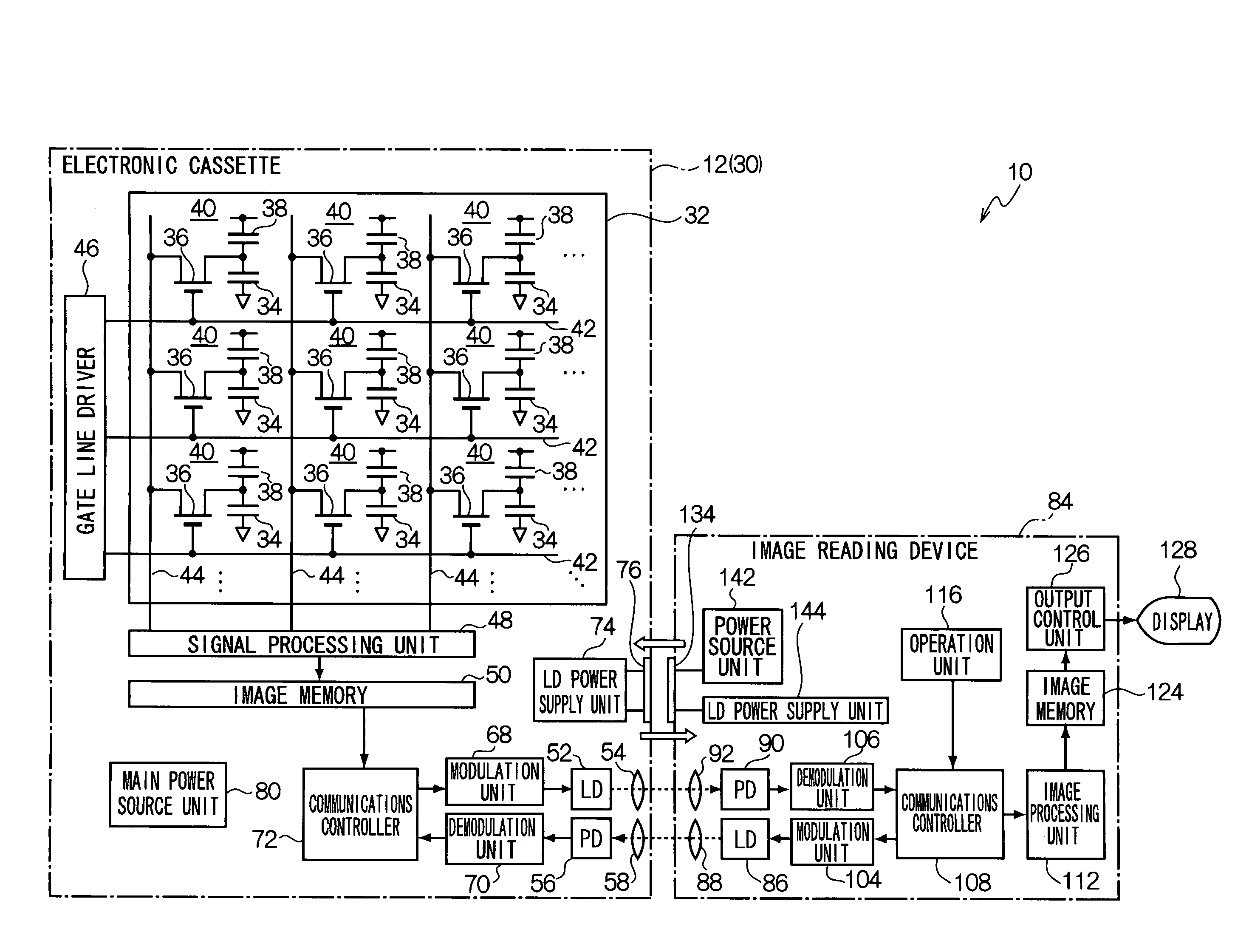
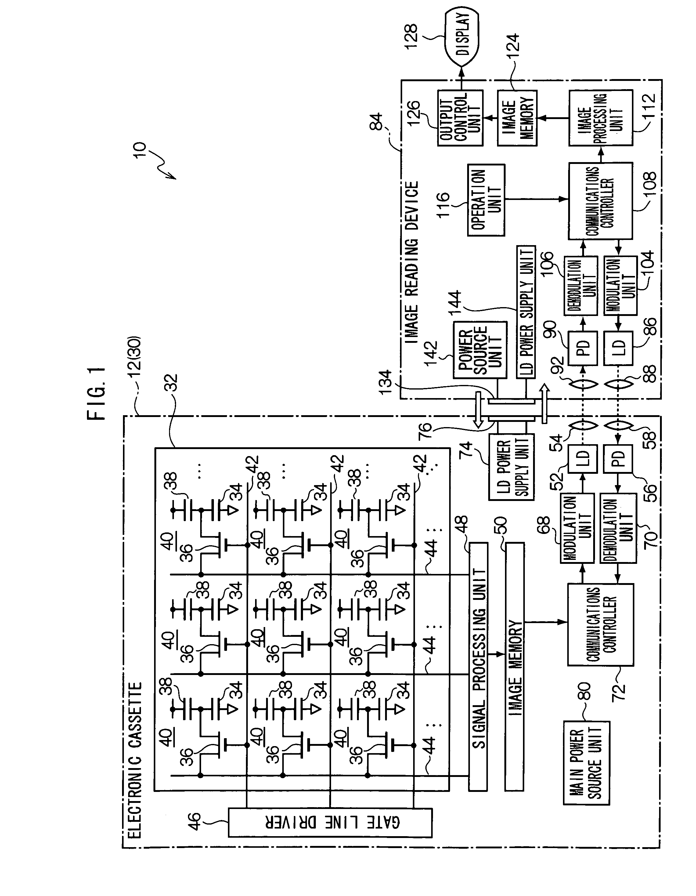
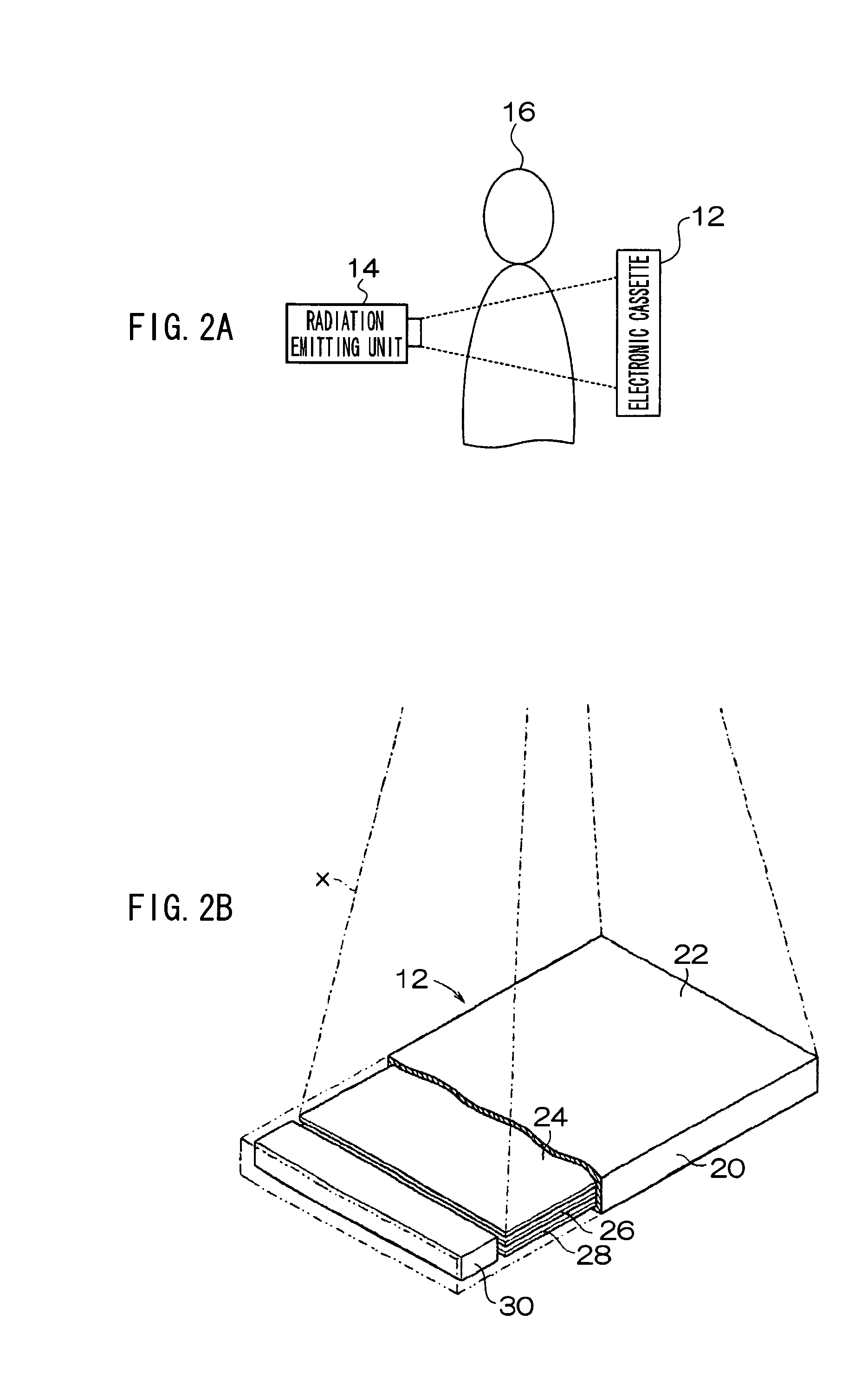
[0035]Explanation will now be given of details of an exemplary embodiment of the present invention, with reference to the drawings. A radiographic imaging handling system 10 according to the present exemplary embodiment is shown in FIG. 1. The radiographic imaging handling system 10 is configured to include a portable electronic cassette 12, the electronic cassette 12 being capable of converting into image data and storing the image information carried by radiation each time the electronic cassette 12 is irradiated, and to include an image reading device 84 capable of reading out image data stored in the electronic cassette 12. It should be noted that each of the electronic cassette 12 and the image reading device 84 correspond to the electronic device of the present invention. The electronic cassette 12 also corresponds to the portable radiographic image conversion device of the present invention, and the image reading device 84 also corresponds to the image reading device of the p...


PUM


Abstract

The main power source unit of an image read-out device supplies power to an laser diode (LD) power supply unit of an electronic cassette through a contact. The LD power supply unit supplies the supplied power to a laser diode (LD), as power used for emitting laser light, and also supplies a portion of the supplied power to an LD power supply unit of the image read-out device through a contact. The power supplied to the LD power supply unit of the image read-out device is supplied as power for emitting laser light to an LD of the image read-out device. When there is a change in the relative position of the casings of the electronic cassette and the image read-out device, the contact and electrical continuation of the contacts breaks and laser light stops being emitted from the LDs.

Description

CROSS-REFERENCE TO RELATED APPLICATION[0001]This application claims priority under 35 USC 119 from Japanese Patent Application No. 2008-041545, the disclosure of which is incorporated by reference herein.BACKGROUND OF THE INVENTION[0002]1. Field of the Invention[0003]The present invention relates to an electronic device, and in particular relates to an electronic device that transmits and receives information to and from an opposing device by means of laser light modulated according to the transmission information.[0004]2. Description of the Related Art[0005]Recently technologies have been proposed for realizing wireless communication at extremely high transmission speeds (for example 1 Gb / s) using laser light in the infrared wavelength region (KDDI R&D Laboratories, “The Realization of Infrared Wireless Communications at a Transmission Speed of 1 Gbit / s Using a Mobile Telephone” Internet: <URL:http: / / www.kddilabsjp / press / img / 83—1.pdf>, (viewed Jan. 21, 2008)). The expectation...

Claims


Application Information

Patent Timeline
Patent Type & Authority Patents(United States)
IPC IPC(8): H04B10/00A61B6/00G01T1/24G01T7/00G03B42/04H01S5/022H04B10/079H04B10/11H04B10/112
CPCH04B10/1143
Inventor NISHINO, NAOYUKIOHTA, YASUNORIMISAWA, TAKESHIISHIYAMA, EIJIMISAWA, ATSUSHI
Owner FUJIFILM CORP
Why Eureka
Try Eureka