
Fixing device and image forming apparatus including fixing device

a technology of fixing device and fixing roller, which is applied in the direction of electrographic process apparatus, instruments, optics, etc., can solve the problems of increasing power consumption, deteriorating heat generation efficiency, and not following the temperature of the fixing roller when a process speed is increased, so as to reduce the warm-up time, prevent deterioration of heat generation efficiency, and stable heat generation

Active Publication Date: 2012-07-17
SHARP KK
View PDF16 Cites 7 Cited by
  • Summary
  • Abstract
  • Description
  • Claims
  • Application Information

AI Technical Summary

Benefits of technology

[0016]An object of the invention is to provide a fixing device of belt fixing type that uses heat of a resistance heat generating element that generates heat due to being energized to heat a fixing belt, having advantages of obtaining a high-quality fixed image with a uniform temperature distribution in the width and circumferential directions of a fixing belt, achieving stable heat generation by a resistance heat generating element to prevent deterioration of heat generation efficiency, and reducing a warm-up time, and an image forming apparatus including the fixing device.

Problems solved by technology

However, in a fixing roller having an elastic layer, the elastic layer can not sufficiently conduct heat, thus, in a case where a heating section is provided inside the fixing roller, there is a problem that a temperature of the fixing roller is not followed when a process speed is increased.
On the other hand, when a diameter of the fixing roller is increased, there is a problem that it takes longer time to warm up or power consumption is increased.
In the fixing device disclosed in JP-A 2006-72182, the difference in temperature on the surface of the heat radiating member in the axial direction thereof can be eliminated; however, when the heat generating member does not heat the entire surface of the heat radiating member, the difference in temperature of the heat radiating member in the circumferential direction thereof (the rotation direction of the fixing belt) may not be eliminated, which results in deterioration in the heating efficiency of the heat radiating member for the fixing belt.
As a result, defective fixing occurs, which results in defective image quality, such as gloss irregularity.
As a result, defective fixing may occur.
When the difference in temperature extremely increases, self-suppression of energization may occur in the resistance heat generating element due to an increase in electrical resistance of the resistance heat generating element or the resistance heat generating element may be damaged due to thermal shock.
Then, heat generation of the heat generating member becomes unstable, and heat generation efficiency is deteriorated.

Method used


Image

  • Fixing device and image forming apparatus including fixing device
  • Fixing device and image forming apparatus including fixing device
  • Fixing device and image forming apparatus including fixing device

Examples


first embodiment

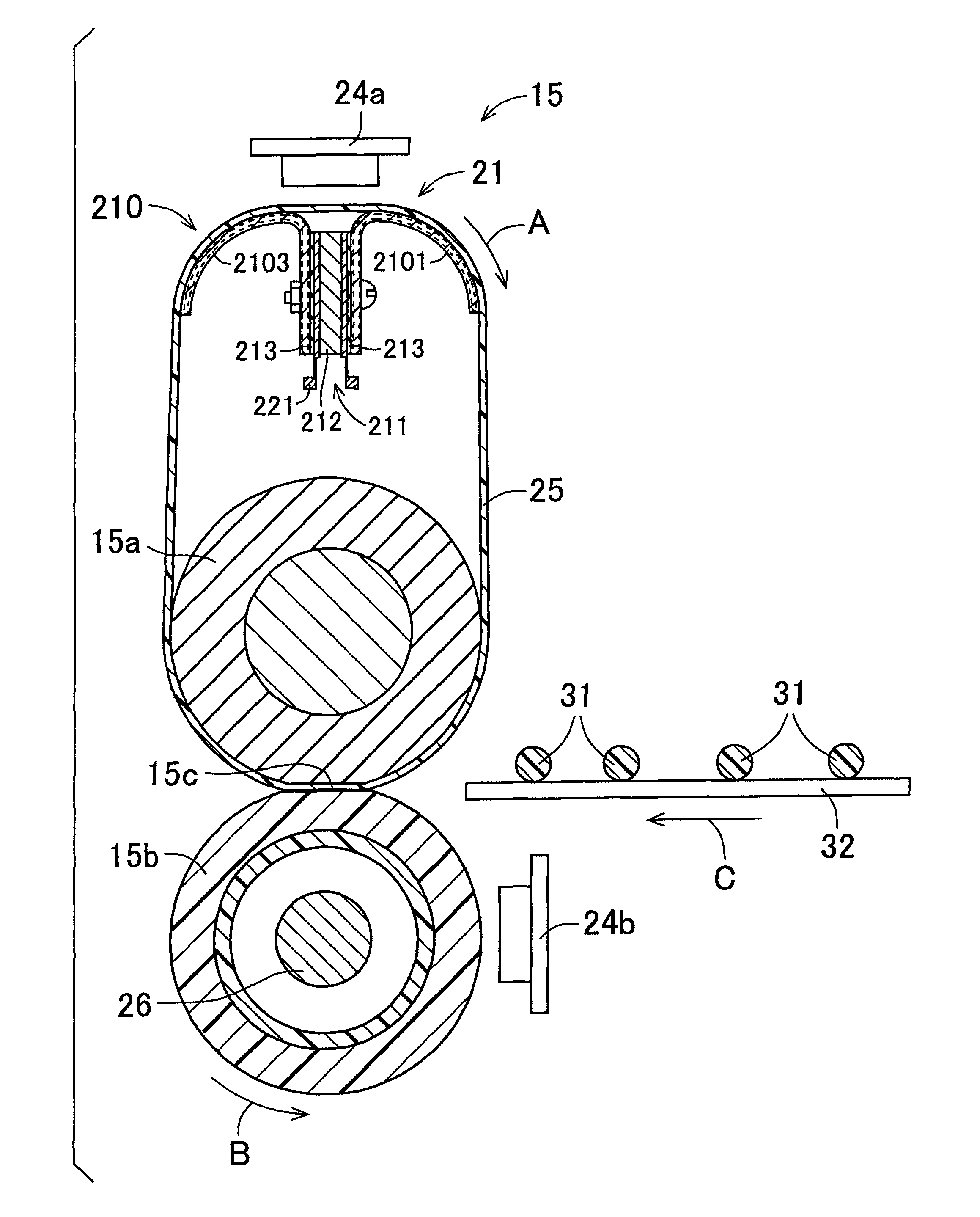
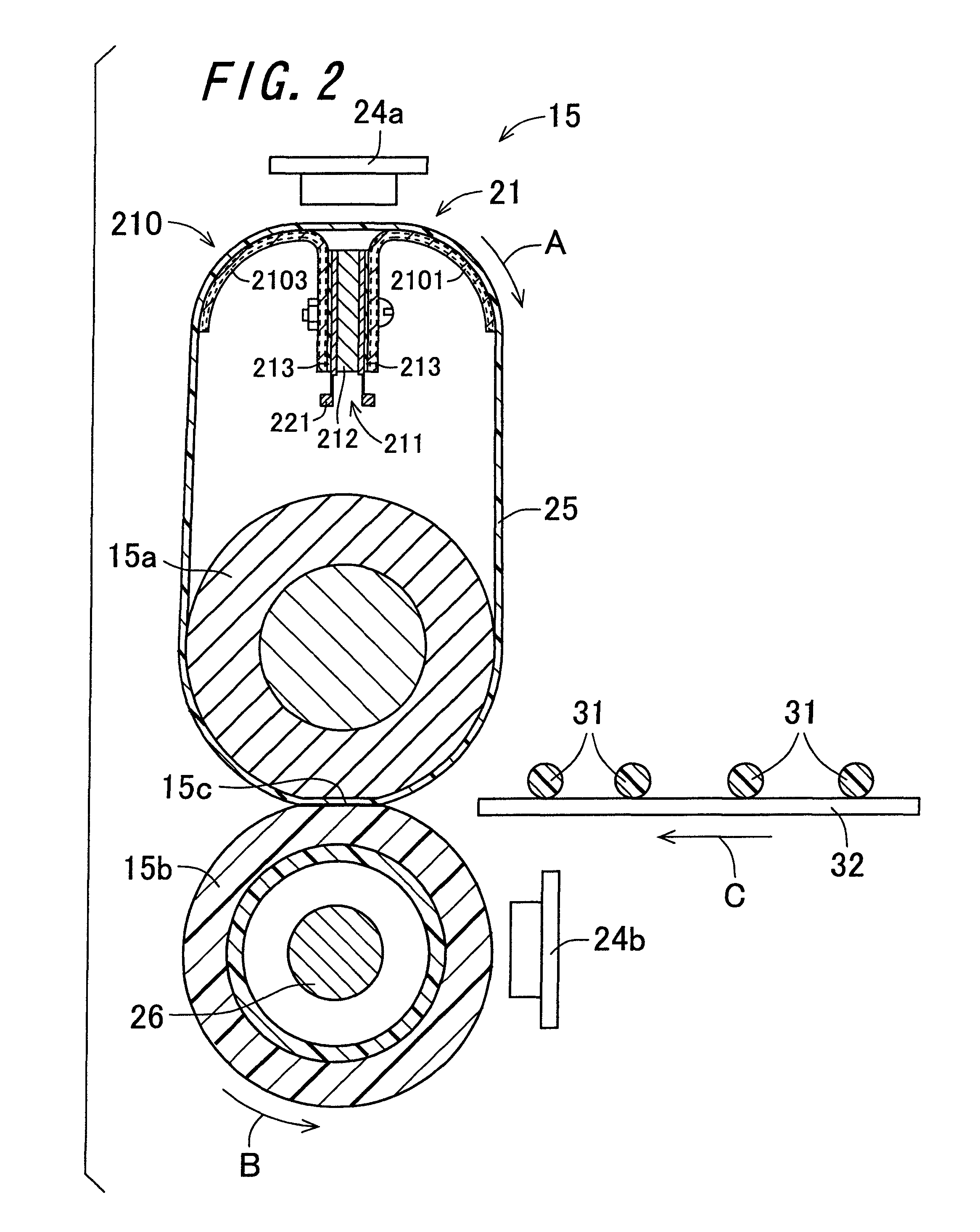
[0114]FIG. 2 is a view showing the structure of the fixing device 15 according to the invention. The fixing device 15 includes a fixing roller 15a serving as a first fixing member, a pressure roller 15b serving as a second fixing member, a fixing belt 25 serving as an endless-shaped belt, and a heating member 21. In the fixing device 15, the fixing belt 25 is supported around the fixing roller 15a and the heating member 21 with tension, and the pressure roller 15b is disposed so as to face the fixing roller 15a, with the fixing belt 25 interposed therebetween. Moreover, the fixing roller 15a and the heating member 21 are arranged substantially in parallel with each other in an axial direction of the fixing roller 15a. With this arrangement, the fixing belt 25 supported around the fixing roller 15a and the heating member 21 with tension can be prevented from running windingly during its sliding movement, wherefore the durability of the fixing belt 25 can be maintained at a high level...

second embodiment

[0215]FIG. 15 is a view showing the configuration of a fixing device 440 according to the invention. The fixing device 440 is a fixing device of two-stage fixing type, and includes a first fixing section 450 that performs primary fixing of the unfixed toner images 31 onto the recording paper sheet 32 under application of heat and pressure, and a second fixing section 460 that is arranged on the downstream side in the conveyance direction of the recording paper sheet 32 from the first fixing section 450 and performs secondary fixing of the toner images 31 after the primary fixing onto the recording paper sheet 32 under application of heat and pressure. The first fixing section 450 and the second fixing section 460 are arranged side by side in the horizontal direction. In the fixing device 440, the first fixing section 450 and the second fixing section 460 are the fixing device 15 of the above-described embodiment that includes the heating member, in which the heat radiating member ha...

third embodiment

[0245]FIG. 16 is a view showing the configuration of a fixing device 470 according to the invention. The fixing device 470 is a fixing device of two-stage fixing type, and includes a first fixing section 480 that performs primary fixing of the unfixed toner images 31 onto the recording paper sheet 32 under application of heat and pressure, and a second fixing section 490 that performs secondary fixing of the toner image 31 after the primary fixing onto the recording paper sheet 32 under application of heat and pressure, the second fixing section being configured by a pair of heating and pressure rollers 491 that are provided with a heating section in an interior thereof, and are in pressure-contact with each other, and being arranged on the downstream side in the conveyance direction of the recording paper sheet 32 with respect to the first fixing section 480. The first fixing section 480 and the second fixing section 490 are arranged side by side in the horizontal direction. In the...


PUM


Abstract

A fixing device is provided. In a fixing device, a heating member that heats a fixing belt includes a heat generating member that has a heat generating layer that generates heat due to being energized, and a heat radiating member. In the heat radiating member, a heat receiving piece of a first heat radiating section and a heat receiving piece of a second heat radiating section are combined with each other to form a heat receiving section, and a heat transfer piece of the first heat radiating section and a heat transfer piece of the second heat radiating section are combined with each other to form a heat transfer section. Heat pipes that are meandering capillary tube heat pipes are formed inside the first heat radiating section and the second heat radiating section.

Description

CROSS-REFERENCE TO RELATED APPLICATION[0001]This application claims priority to Japanese Patent Application No. 2009-129584, which was filed on May 28, 2009, the contents of which are incorporated herein by reference in its entirety.BACKGROUND OF THE INVENTION[0002]1. Field of the Invention[0003]The present invention relates to a fixing device that fixes a toner image onto a recording medium by the action of heat and pressure, and to an image forming apparatus including the fixing device.[0004]2. Description of the Related Art[0005]As a fixing device for use in an electrophotographic image forming apparatus such as a copying machine and a printer, a fixing device of heat-roller fixing type has been in wide use. The fixing device of heat-roller fixing type includes a pair of rollers (a fixing roller and a pressure roller) that are brought into contact with each other under pressure. By means of a heating section composed for example of a halogen lamp, which is placed in each of or on...

Claims


Application Information

Patent Timeline
Patent Type & Authority Patents(United States)
IPC IPC(8): G03G15/20
CPCG03G15/2064G03G2215/2029
Inventor MITSUOKA, TETSUNORI
Owner SHARP KK
Learn More