Snaking robotic arm with movable shapers

a robotic arm and shaper technology, applied in the direction of arms, machine supports, program-controlled manipulators, etc., can solve the problems of not being able to adjust into new positions, not being able to adjust to the force acting on the column, and being unable to adjust to the new position

Active Publication Date: 2012-07-17
TITAN MEDICAL INC
View PDF16 Cites 91 Cited by
  • Summary
  • Abstract
  • Description
  • Claims
  • Application Information

AI Technical Summary

Benefits of technology

[0018]It is an object of this invention to provide an improved articulable column construction that overcomes the difficulties of column sag and adjustment.
[0019]It is also an object of this invention to provide a method and device that controls the shape of the articulable member, thereby providing a tool platform which can be directed down a tortuous passage, and return, without injury to the device or the body in which it is placed.
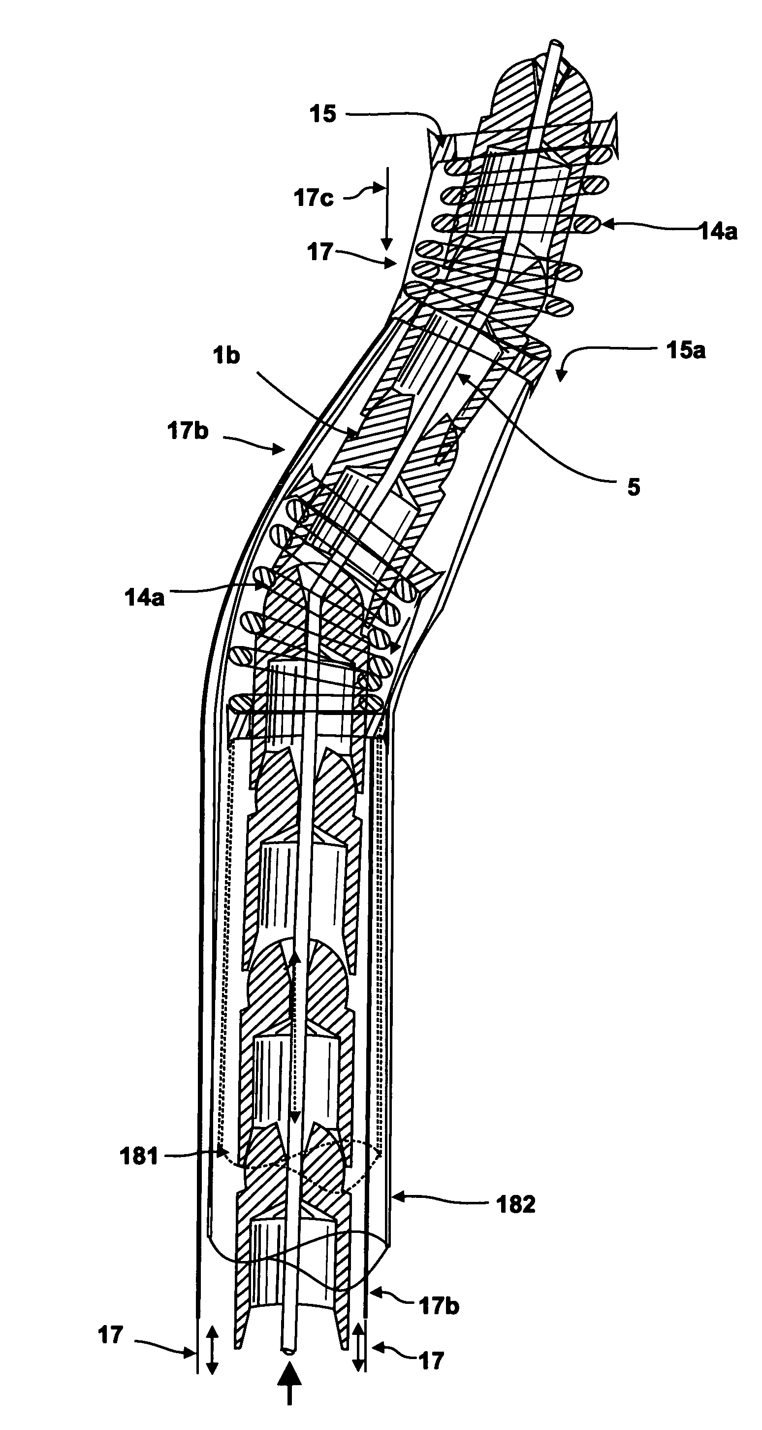
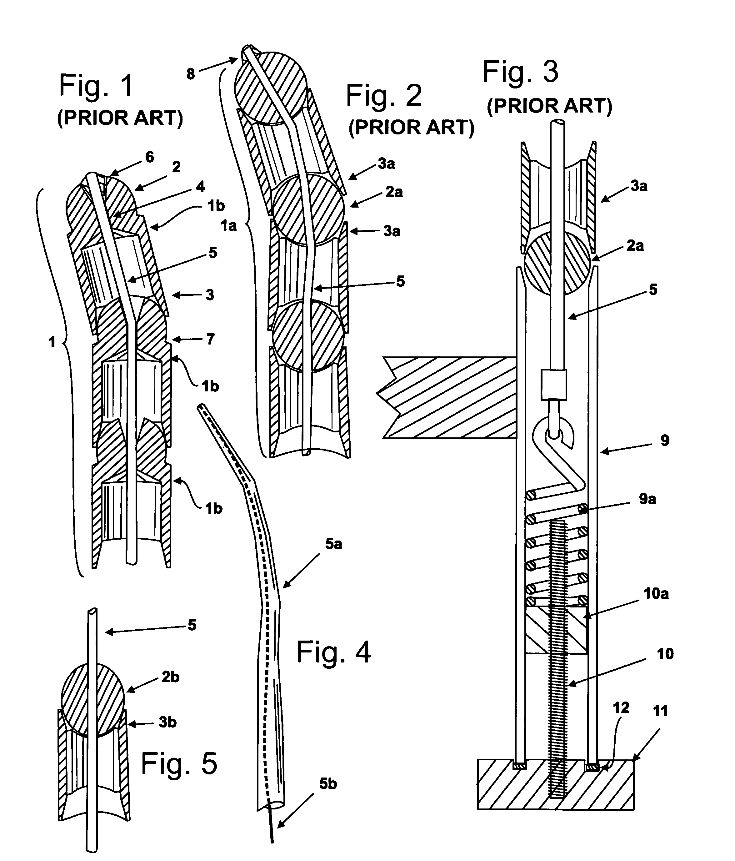
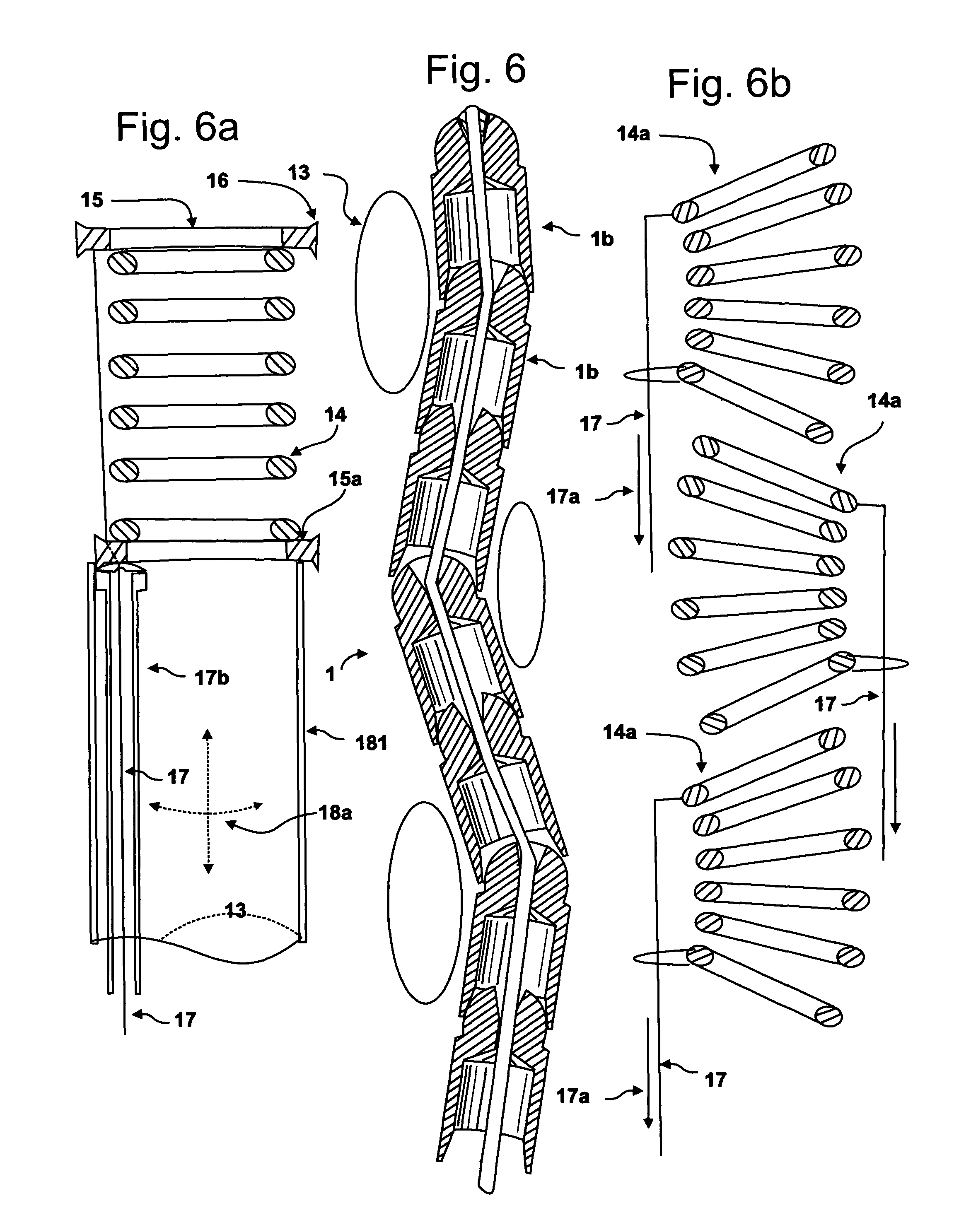
[0020]To accomplish this it is an object of this invention to provide a method for making the articulable column sufficiently stiff by introducing a springing member to the centre of the column in place of or in addition to the cable, which conventional articulable columns rely on. This springing member / compressing member 5a may have, but need not have, a variable modulus from one end to the other, for example, high modulus on the proximal end and lower modulus on the distal end, resulting in a column that will have stiff proximal or base joints where acting forces are large and (2) are relatively flexible at joints near the distal or free end where acting forces are smaller. This allows columns to be built which are slender, articulable, structural members which can support large free end loads, and / or long column lengths. Columns built with this method also can be articulated in a natural, effective fashion. It also allows the articulable column to be relatively flexible, prior to complete compression, which allows it to be shaped, yet, remain relatively straight in those sections that are not shaped. The springing member / compressing member 5a also gives the articulable column, and robotic arm, a biased shape, usually straight, so that the column returns to the biased shape once it has passed through the shaper. In some preferred embodiments the springing member / compressing member 5a is responsible for all or virtually all of the biased shape, while in other preferred embodiments, the biased shape is supplemented by the contribution of other components of the arm, such as the communicating tubes 181, 182. In other embodiments of the invention these said other components are designed to act as the sole springing element in which event a compression cable, referred to as a compressing member 5 will be required. The springing member / compressing member 5a may be made of any materials and designs, well known to the art. For example, it might be made of stainless steel or superlastic nickel-titanium and be solid or tubular, or of any suitable cross-section, or be a coiled spring. In some preferred embodiments, the compressing member 5 may also be used exclusively or in combination with cables or other members to put the segments of the articulable column into compression, thereby making it more rigid. In other preferred embodiments, the springing member / compressing member 5a is used solely to provide a springing support to the articulable column, leaving the compression of the segments comprising the said column to other members, such as compressing member 5b, which in some preferred embodiments are contained within the lumen of the springing element. It should be noted that since the springing member / compressing member 5a may also act as a compressing member, it is sometimes referred to as a compressing member.
[0024]The present invention includes a selected number of shapers which can be moved up and down the articulable column and rotated around it. As the arm advances or exits the body, the shapers are given a suitable shape and location on the column to avoid the obstruction, and then set in that position, relative to the body, allowing the relatively flexible articulable column and outer skin to assume the shape of the shaper continuously as they advance and exit, over and / or within the shapers. As they exit the shaper, they return to their biased shape (usually straight) and advance until the next shaper is deployed, which in turn guides them through the next curvaceous turn. Thus, the arm self-computes the cascade of movements. The arm then operates in two modes, the first, a low energy mode in which the arm flexes easily, and responds to the shaper's directional changes; second, when the site is reached, a high energy mode, when the segments of the column are put into compression, creating a rigid member of the required shape, that can stably support the tools at the distal end of the arm and exert the necessary force to execute the work.
[0036]The articulable column is transformable from a low energy state in which said joints are freely movable so as to produce bending in said column, and a high energy state in which at least one of said joints is compressed so as to constrain its movement and thereby increase rigidity in the column along at least part of its length.
[0039]The compression control mechanism controls rigidity of said articulable column, wherein said compression control mechanism selectively actuates one or more of said compression elements so as to reversibly and controllably produce compression in at least one of said joints.

Problems solved by technology

The disadvantage to prior art columns is that they are not adapted to accommodate the forces acting on the column.
Consequently they tend to sag when extended out horizontally to the floor and they are difficult to adjust into new positions.
Adjustment of these columns by gripping the column at the free end is also difficult because, if partially locked, the column remains stiff at the free end while persistently bending at the weakest base joint, or if tension in the column is completely released, the column collapses.
However, for long columns it is an unwieldy and inelegant method and difficult to manufacture.
The difficulty with this design is that the surfaces of many of the socket joints must be machined to different specifications.

Method used


Image

  • Snaking robotic arm with movable shapers
  • Snaking robotic arm with movable shapers
  • Snaking robotic arm with movable shapers

Examples


Embodiment Construction

[0093]FIGS. 1, 2 and 3 illustrate the existing art. FIG. 1 illustrates a typical articulable column 1, which is comprised of segments 1b, each having a ball 2 on one end and a socket 3 or receiver on the other. The movement of each segment is limited by a shoulder 7. Each segment 1b also has a lumen 4 through which a flexible cable, the compressing member 5 passes. One end of the cable or compressing member 5 is connected to the most distal segment by connecting means, such as a swage 6, and at the proximal end by a spring 9a, and turnbuckle comprised of a threaded spring retaining block 10a threaded stud 10, thumbscrew 11 and bearing 12; all contained within a retaining tube 9. The cable or compressing member 5 is generally tightened somewhat, providing sufficient friction, with the cooperation of the spring 9a, to arrange the articulable column, herein referred to as the “initial friction”. Once in place the cable is further tightened so that it becomes rigid. FIG. 2 illustrates a...


PUM


Abstract

Presented is a method and apparatus comprising one or more robotic members which are curvaceous or snake-like; having movable shapers through which may pass an articulable column having successive joints formed of alternating ball and socket members. The shapers can be directed up and down the articulable column, to create virtually any radius of curvature, in any direction. The robotic member may also include discrete microelectronic mechanical devices (MEMS) shapers with embedded addressable controllers. Thus the device, with computerized control is capable of negotiating a tortuous path to access the site of a given operation and to retreat along the same path, without injury to the body in which the arm is directed. Once at the work site, the articulating columns, or parts of them, may be put in compression, causing them to become rigid.

Description

BACKGROUND OF THE INVENTION[0001]1. Field of the Invention[0002]This invention relates to a method and means for building an improved robotic arm and fingers that are snake-like, and which is composed of an articulable column, composed of segmented members that while flexible are shaped by shaping elements through which the articulable column passes and discrete microelectronic mechanical systems (MEMS) that shape the column. Once the snaking columns have reached the work site, all or parts of them are transformed into a rigid work platform by compressing various parts of the segmented members by means of compressing members, while still maintaining its shape.[0003]2. Description of Prior Art[0004]Articulable columns have long been known for use in positioning micrometers and other measurement tools, or as electric light stands.[0005]U.S. Pat. No. 599,543 discloses a support for incandescent electric lamps where the column is composed of a series of ball / socket members. An extension...

Claims


Application Information

Patent Timeline
Patent Type & Authority Patents(United States)
IPC IPC(8): G06F19/00
CPCB25J9/06B25J18/06F16M11/14F16M11/18F16M11/40B25J9/065F16M11/2078Y10T74/20329F16M2200/041F16M2200/044
Inventor UNSWORTH, JOHN
Owner TITAN MEDICAL INC
Why Eureka
Try Eureka