
Wall panel assembly

a wall panel and assembly technology, applied in the direction of instruments, curtain suspension devices, signs, etc., can solve the problems of increasing the amount of time and hardware required to mount the panels, affecting the safety of people and property below, and the brackets and mounting of the panels are difficult to align and mount, so as to prevent accidental separation of the clip and the panel. , the effect of easy sliding

Active Publication Date: 2012-07-24
SAGAMORE PARTNERS
View PDF14 Cites 24 Cited by
  • Summary
  • Abstract
  • Description
  • Claims
  • Application Information

AI Technical Summary

Benefits of technology

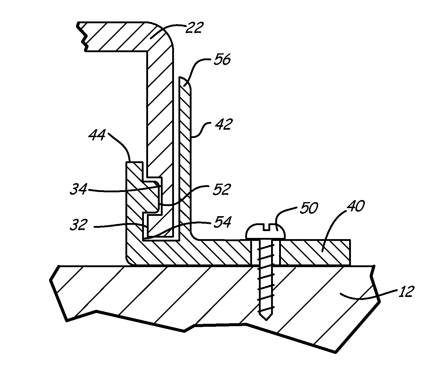
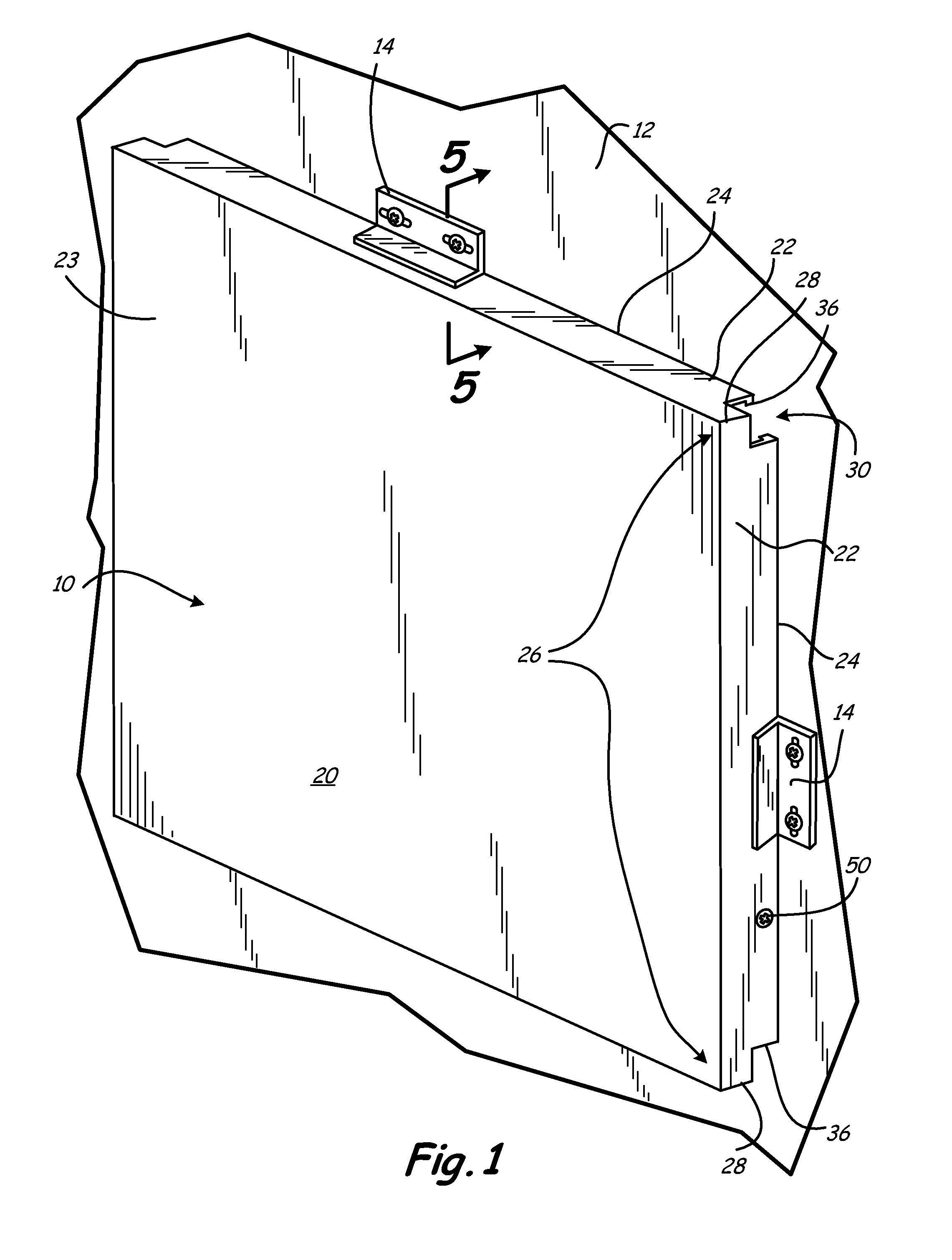
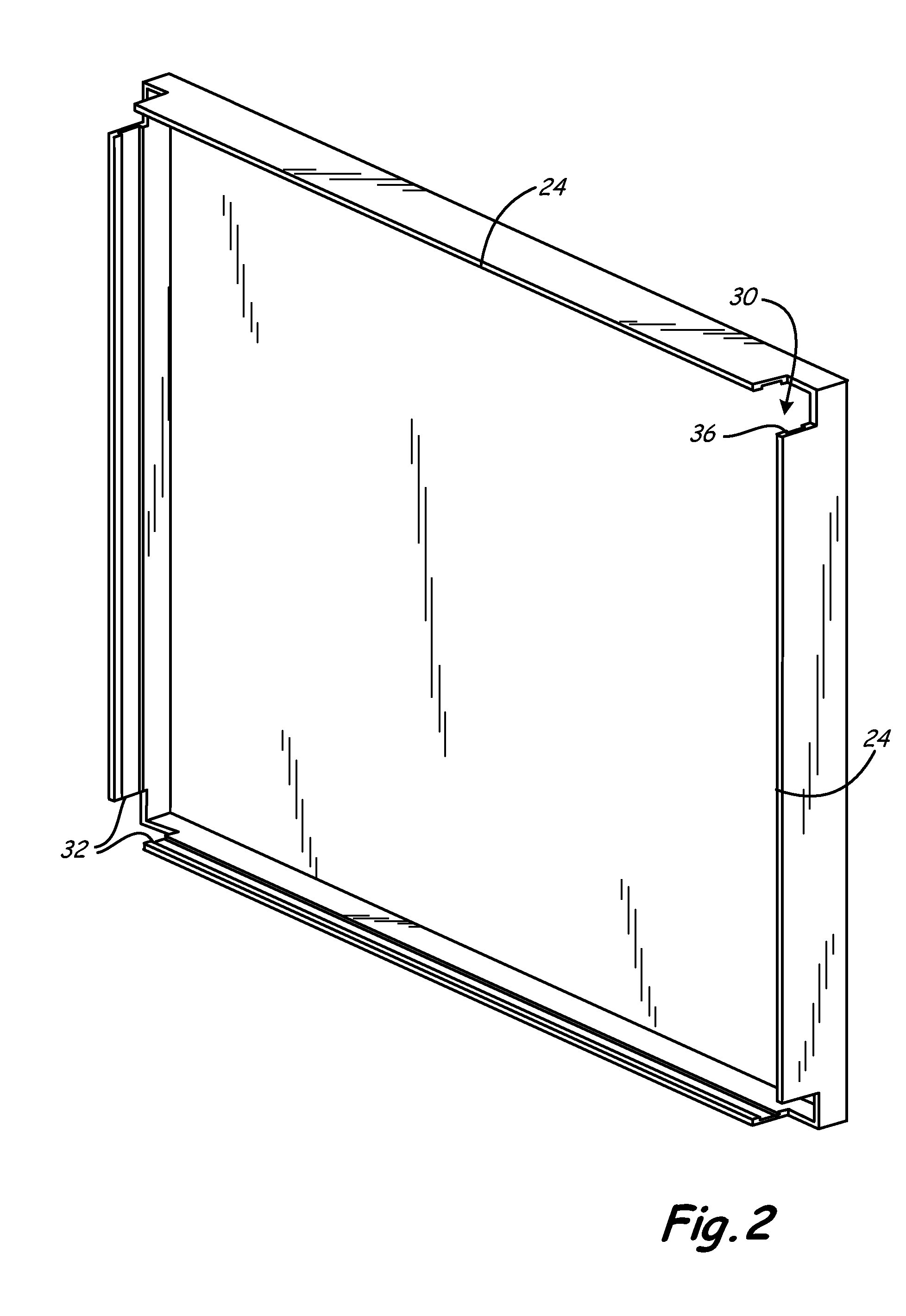
"The present invention is a special panel and clip arrangement for mounting a panel to a building wall or column. The clip is easily slidably mounted on the panel at a limited number of mounting locations along the peripheral edge of the panel, typically one or more corners of the panel. The clip can be slid along the panel to a desired location for optimally securing the panel to a wall. The panel is a generally rectangular pan with sides extending rearward from a front surface of the panel. The clip includes a fastening leg, a track leg and a restraining leg. The clip is always visible in the mounting process and can be easily adjusted to a desired location along the panel sides. The invention allows for easy and secure mounting of panels to walls and provides decorative and protective covers or surfaces on the front of the panel as desired."

Problems solved by technology

When the panel is raised in front of the wall brackets for mounting, neither the first or second set of brackets can readily be seen, making alignment of the brackets and mounting of the panel more difficult.
Further, two sets of brackets must be used to hang the panel, increasing the amount of time and hardware required to mount the panels.
Panels secured to the exterior of buildings, particularly tall buildings, pose a threat to persons and property below if they were to come loose from the building.

Method used


Image

  • Wall panel assembly
  • Wall panel assembly
  • Wall panel assembly

Examples


Embodiment Construction

[0031]Even though numerous characteristics and advantages of the present invention have been set forth in the following description, together with details of the structure and function of the invention, the disclosure is illustrative only, and changes may be made in detail, especially in matters of shape, size, and arrangement of parts within the principles of the invention to the full extent indicated by the broad general meaning of the terms in which the appended claims are expressed.

[0032]The present invention provides a method and structure for securing decorative and / or protective panels 10 to a wall 12 by panel clips 14 as shown in FIG. 1. The wall may be an interior or exterior wall or column or other suitable substrate for the panels. The means for fastening the panel clip 14 to the wall 12 may be fasteners of any suitable type, but for the purposes of illustration, common screws are referenced in this disclosure.

[0033]The panel may be of any shape or configuration, by way o...


PUM


Abstract

The present invention is a wall panel assembly for securing a protective and / or decorative panel to a wall, such as the exterior wall of a building. The panel includes a rail and channel arrangement along each edge of the panel designed to slideably engage panel clips having a cooperative guide rail and channel. The clips are used to secure the panel to a wall using common fasteners, such as screws.

Description

FIELD OF THE INVENTION[0001]The present invention relates to decorative and / or protective wall panels for covering interior and exterior building walls and columns.BACKGROUND OF THE INVENTION[0002]There are many known arrangements for securing decorative and / or protective panels to an interior or exterior building wall or column.[0003]U.S. Pat. No. 6,631,589 to Friedman et al. discloses the use of a first set of mounting brackets secured to a wall and a second set of mounting brackets secured to the back of a panel. When the panel is raised in front of the wall brackets for mounting, neither the first or second set of brackets can readily be seen, making alignment of the brackets and mounting of the panel more difficult. Further, two sets of brackets must be used to hang the panel, increasing the amount of time and hardware required to mount the panels. U.S. Pat. No. 2,653,686 to A. Routt provides a similar design of dual brackets, a first bracket mounted to the wall and a second br...

Claims


Application Information

Patent Timeline
Patent Type & Authority Patents(United States)
IPC IPC(8): E04B1/38
CPCE04F13/0803E04F13/0848G09F7/18
Inventor WALLACE, MICHAEL R.
Owner SAGAMORE PARTNERS
Learn More