
Power transmission device

a transmission device and power technology, applied in the direction of gearing, gearing elements, hoisting equipment, etc., can solve the problems of increasing the total gear noise, affecting the operation of the power transmission device, and causing occasional noise, so as to reduce the noise of the gear

Inactive Publication Date: 2012-07-24
TOYOTA JIDOSHA KK
View PDF23 Cites 17 Cited by
  • Summary
  • Abstract
  • Description
  • Claims
  • Application Information

AI Technical Summary

Benefits of technology

[0012]The invention provides a power transmission device in which gear noise is reduced.
[0014]According to the invention, it is possible to provide a power transmission device in which gear noise may be more reduced.

Problems solved by technology

Gear noise may be occasionally produced when the gears provided in the power transmission device are engaged with each other to be driven.
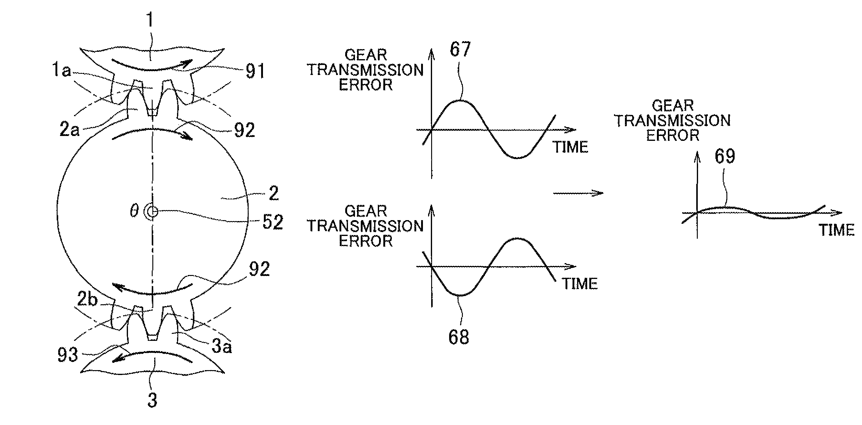
Although the methods described in the publications mentioned above reduce gear noise due to engagement between gears, there is still room left for improvement in the structure of the power transmission device, in which gear noise produced between the first gear and the intermediate gear and gear noise produced between the intermediate gear and the second gear occasionally amplify each other to increase the total gear noise.

Method used


Image

  • Power transmission device
  • Power transmission device
  • Power transmission device

Examples


Embodiment Construction

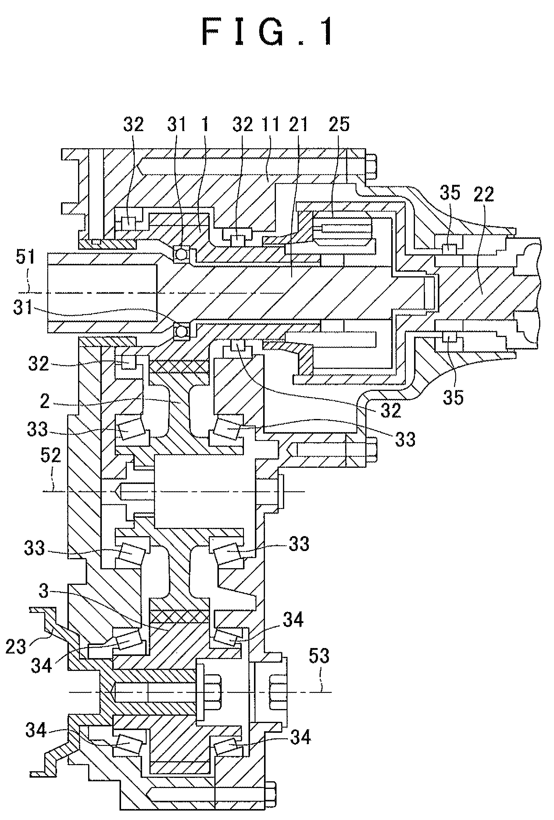
[0030]A power transmission device in accordance with an embodiment of the invention will be described with reference to FIGS. 1 to 13. The power transmission device in accordance with this embodiment may be mounted in a four-wheel drive vehicle.

[0031]The power transmission device is also referred to as “multiple transmission device.” The power transmission device is connected to the output side of a transmission. The rotational force (driving force) of an engine is input to the transmission, and the rotational force output from the transmission is input to the power transmission device.

[0032]The power transmission device distributes and outputs the rotational force output from the transmission to a front propeller shaft for front wheels and a rear propeller shaft for rear wheels. For example the power transmission device may transmit 60% of the input rotational force to the rear propeller shaft and 40% of the input rotational force to the front propeller shaft. The front propeller s...


PUM


Abstract

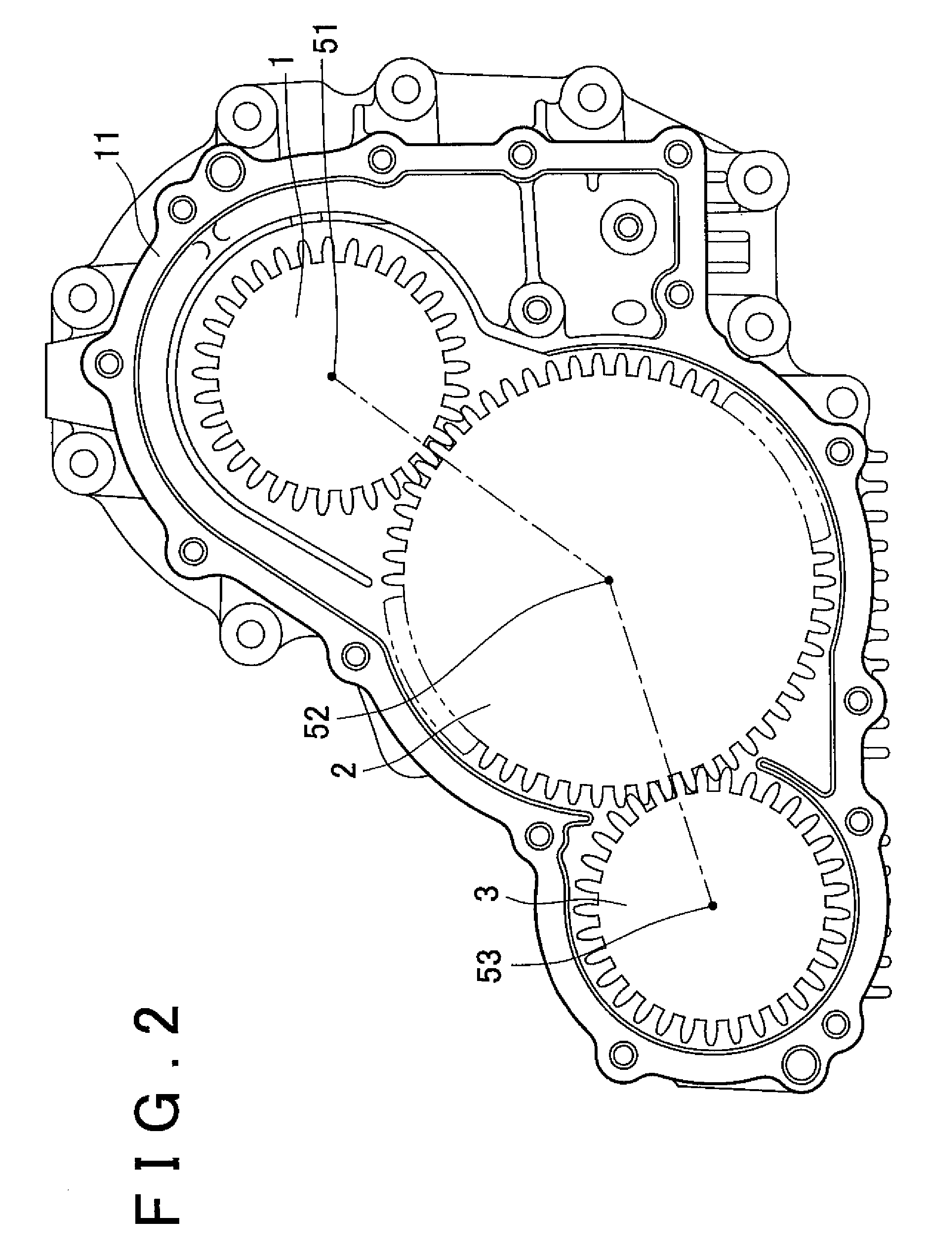
A power transmission device is provided with: a first gear having a plurality of teeth that share an identical tooth profile; an intermediate gear that is engaged with the first gear; and a second gear that is engaged with the intermediate gear, and has a plurality of teeth that share an identical tooth profile, wherein the first gear and the second gear have an identical number of teeth, an identical reference diameter, and an identical reference pitch; and the tooth profile of the first gear is different from that of the second gear.

Description

INCORPORATION BY REFERENCE[0001]The disclosure of Japanese Patent Application No. 2007-038123 filed on Feb. 19, 2007 including the specification, drawings and abstract is incorporated herein by reference in its entirety.BACKGROUND OF THE INVENTION[0002]1. Field of the Invention[0003]The invention relates to a power transmission device.[0004]2. Description of the Related Art[0005]A power transmission device transmits power from one device to another. Some power transmission devices include a plurality of gears engaged with each other. Four-wheel drive vehicles and large six-wheel drive vehicles, for example, have a power transmission device that distributes driving force between the front wheels and rear wheels.[0006]The power transmission device includes three gears: a drive gear to which power from an engine is input, an idler gear for that engages the drive gear, and a driven gear that engages the idler gear.[0007]Japanese Utility Model Application Publication No. 06-025652 descri...

Claims


Application Information

Patent Timeline
Patent Type & Authority Patents(United States)
IPC IPC(8): F16H55/14F16H55/00
CPCF16H1/20F16H57/0006F16H55/088F16H55/0886Y10T74/19949Y10T74/19907Y10T74/19972
Inventor SHIMADA, YUJIKOBAYASHI, KATSUYA
Owner TOYOTA JIDOSHA KK
Learn More