Device for mounting an aircraft turboprop engine comprising hydraulic attachments

a technology for aircraft turboprop engines and hydraulic attachments, which is applied in the direction of machines/engines, machine supports, other domestic objects, etc., can solve the problems of substantial mechanical stress and extremely complex determination, and achieve the effect of dampening vibrations

Active Publication Date: 2012-07-24
AIRBUS OPERATIONS (SAS)
View PDF26 Cites 17 Cited by
  • Summary
  • Abstract
  • Description
  • Claims
  • Application Information

AI Technical Summary

Benefits of technology

[0012]With this isostatic character of the assembly, the determination of the efforts at the interfaces is facilitated, and the assembly considerably simplified, since it is free of mechanical stresses.
[0017]In addition, the fact that there are several hydraulically connected jacks greatly assists with the transmission of the efforts being exerted according to the degrees of freedom of rotation of the turboprop engine.
[0018]Preferably, at least one of the said six hydraulic systems, and even more preferably each of them, comprises a dampening system, to dampen the vibrations caused essentially by the propeller.

Problems solved by technology

Consequently, the constructed assembly is totally hyperstatic, such that the efforts at the interfaces depend on the relative flexibility of the engine, the structure and the attachments, the manufacturing tolerances and the thermal differential distortions, making it extremely complex to determine them.
In addition, the hyperstatic nature of these attachment devices may lead to assembly difficulties, and also lead to the appearance of substantial mechanical stresses.

Method used


Image

  • Device for mounting an aircraft turboprop engine comprising hydraulic attachments
  • Device for mounting an aircraft turboprop engine comprising hydraulic attachments
  • Device for mounting an aircraft turboprop engine comprising hydraulic attachments

Examples


Embodiment Construction

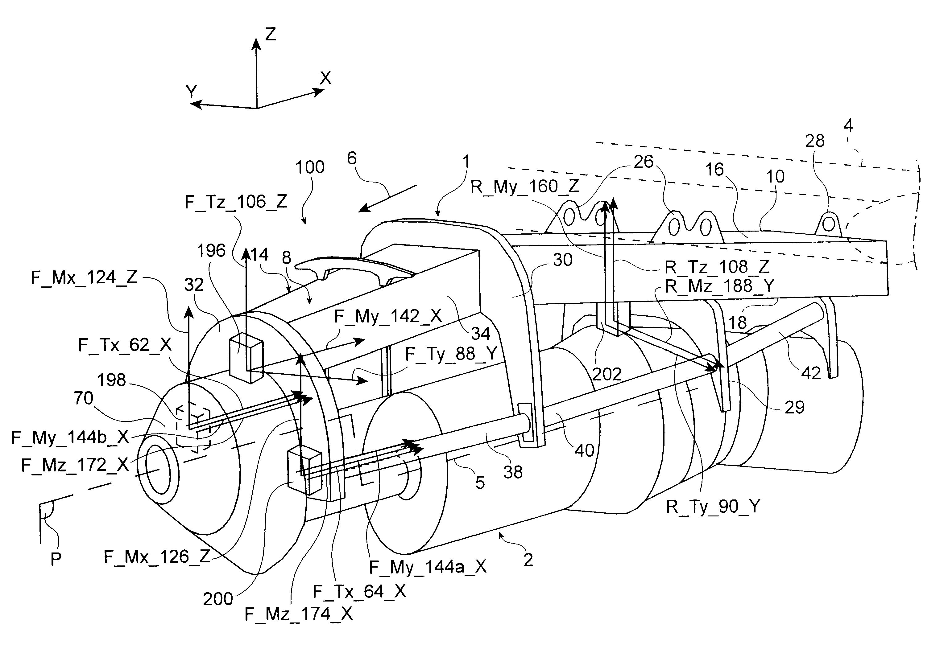
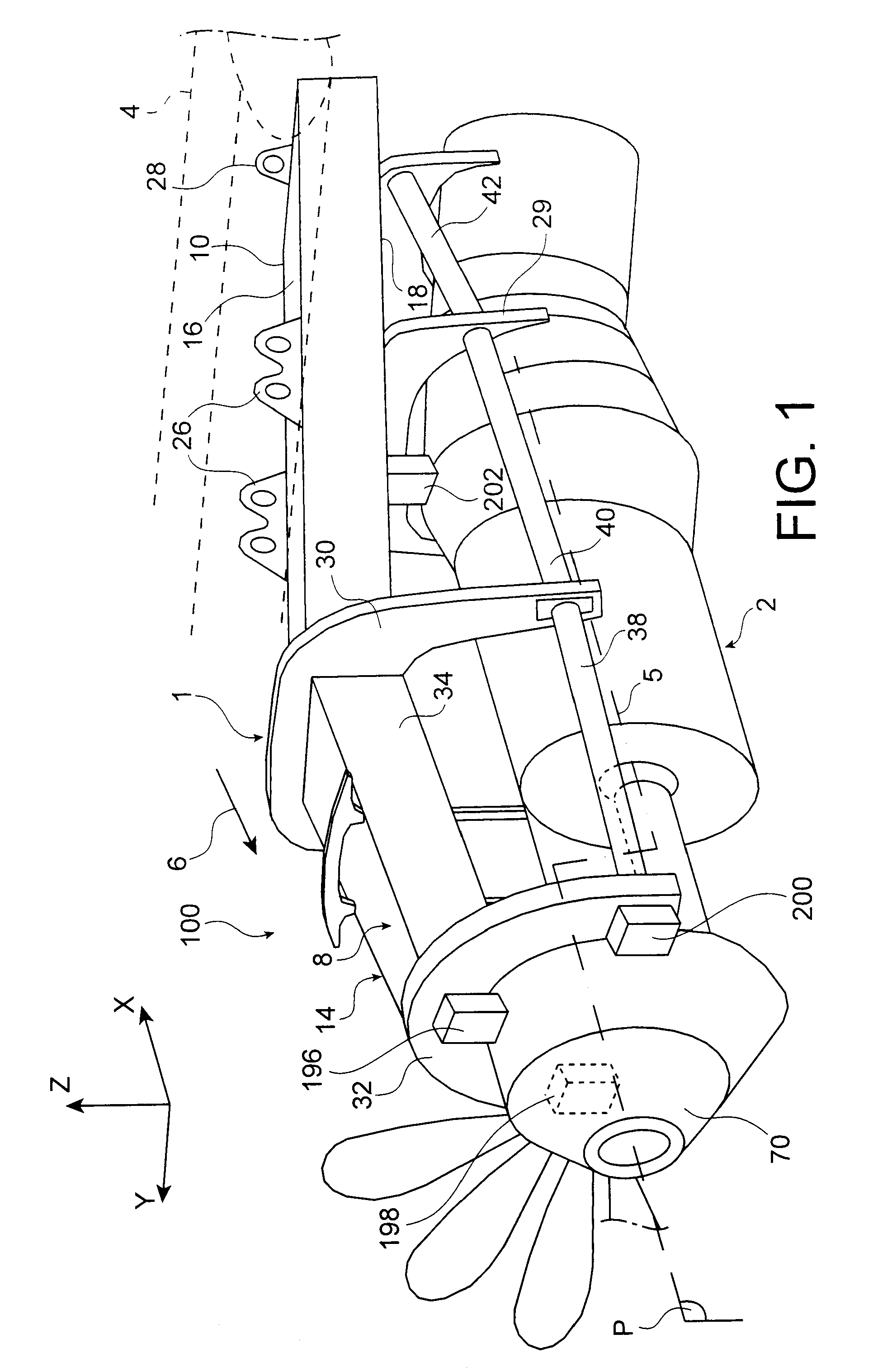
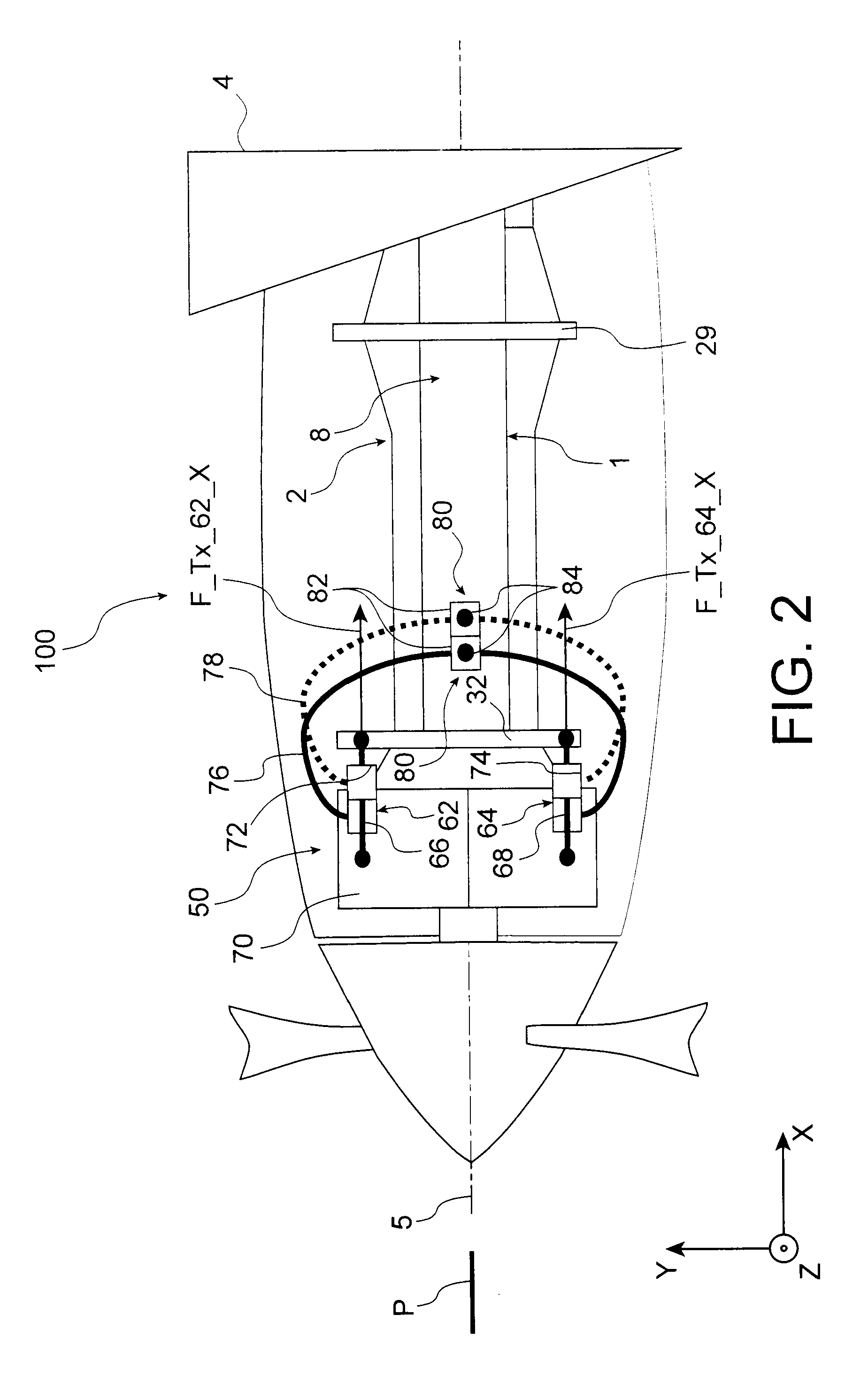
[0029]With reference to FIG. 1, an engine unit 100 for an aircraft according to a preferred embodiment of the present invention can be seen; this unit 100 globally comprises a turboprop engine 2, and also an engine mounting structure or device 1. Device 1 is here intended to provide the suspension of turboprop engine 2 under a wing of an aircraft represented only diagramatically for obvious reasons of clarity, and designated in a general manner by numerical reference 4.

[0030]Throughout the disclosure which will follow, by convention, X is the name given to the direction parallel to longitudinal axis 5 of the turboprop engine 2, also comparable to the longitudinal direction of structure 1 and of unit 100, Y is the direction oriented transversally relative to the aircraft and to turboprop 2, and also comparable to the transverse direction of structure 1 and of unit 100, and Z is the vertical direction, or direction of the height; these three directions are orthogonal one to the others...


PUM


Abstract

An engine unit for an aircraft including a turboprop engine and its device for mounting on to a wing surface. The device includes a rigid structure and a mechanism for fastening the turboprop engine on to this structure. The fastening mechanism includes six mutually independent hydraulic systems, each one exclusively dedicated to the transfer, to the rigid structure, of forces exerted respectively according to one of the six degrees of freedom of movement. Each hydraulic system includes at least one hydraulic jack with a piston attached to one of the two elements, i.e. either the turboprop engine or the rigid structure, together with a cylinder housing the piston and attached to the other of the two elements.

Description

TECHNICAL FIELD[0001]The present invention relates generally to a device able to mount a turboprop engine under an aircraft wing surface, or again above this same wing surface.[0002]Such a device may be used on any type of aircraft having turboprop suspended engines or engines mounted above its wing surface, such as turboprop engines able to supply a very high level of power, possibly exceeding 10,000 horsepower.STATE OF THE PRIOR ART[0003]In existing aircraft the engines are suspended beneath or mounted above the wing surface by complex mounting systems, also called “EMS” (“Engine Mounting Structure”), in order jointly to form an assembly called an engine unit.[0004]These devices are designed notably to allow transmission to the wing surface of the static and dynamic efforts produced by the engines, such as the weight, the thrust or again the various dynamic efforts. All references hereinafter to efforts shall be understood and considered to include reference to forces.[0005]In the...

Claims


Application Information

Patent Timeline
Patent Type & Authority Patents(United States)
IPC IPC(8): F02C7/20
CPCB64D27/12B64D2027/264
Inventor MARCHE, HERVE
Owner AIRBUS OPERATIONS (SAS)
Why Eureka
Try Eureka