
Method and apparatus for determining dynamic deformation characteristics of an object

a dynamic deformation and characteristic technology, applied in the direction of apparatus for force/torque/work measurement, instruments, applications, etc., can solve the problem of limited size of the corneal region being characterized, and achieve the effect of facilitating the quantitative determination of elastic and viscoelastic properties

Active Publication Date: 2012-07-24
VISION OPTIMIZATION
View PDF14 Cites 9 Cited by
  • Summary
  • Abstract
  • Description
  • Claims
  • Application Information

AI Technical Summary

Problems solved by technology

The size of the corneal region being characterized may be limited by the operable distance of the corneal surface from the apparatus.

Method used


Image

  • Method and apparatus for determining dynamic deformation characteristics of an object
  • Method and apparatus for determining dynamic deformation characteristics of an object
  • Method and apparatus for determining dynamic deformation characteristics of an object

Examples


Embodiment Construction

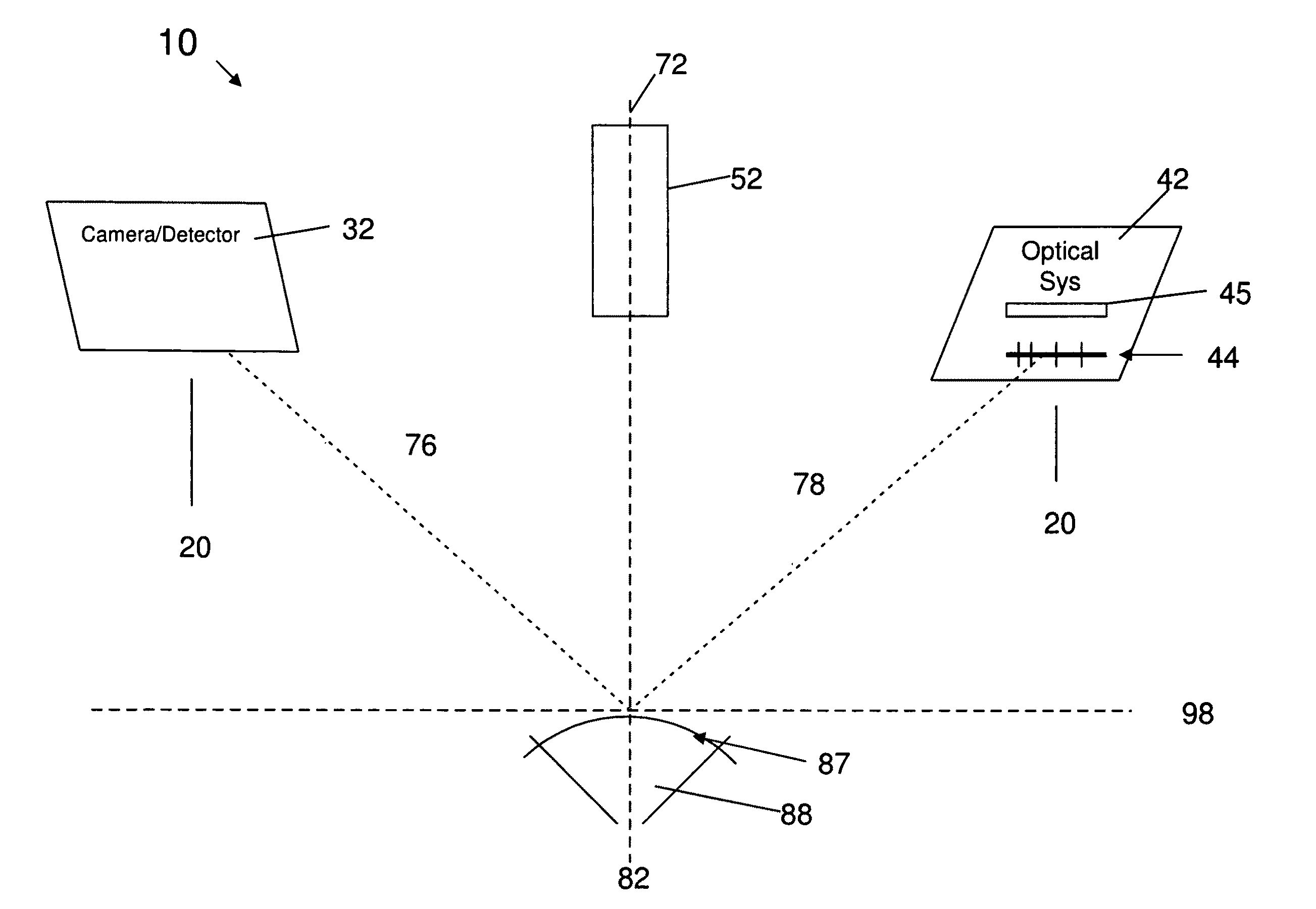
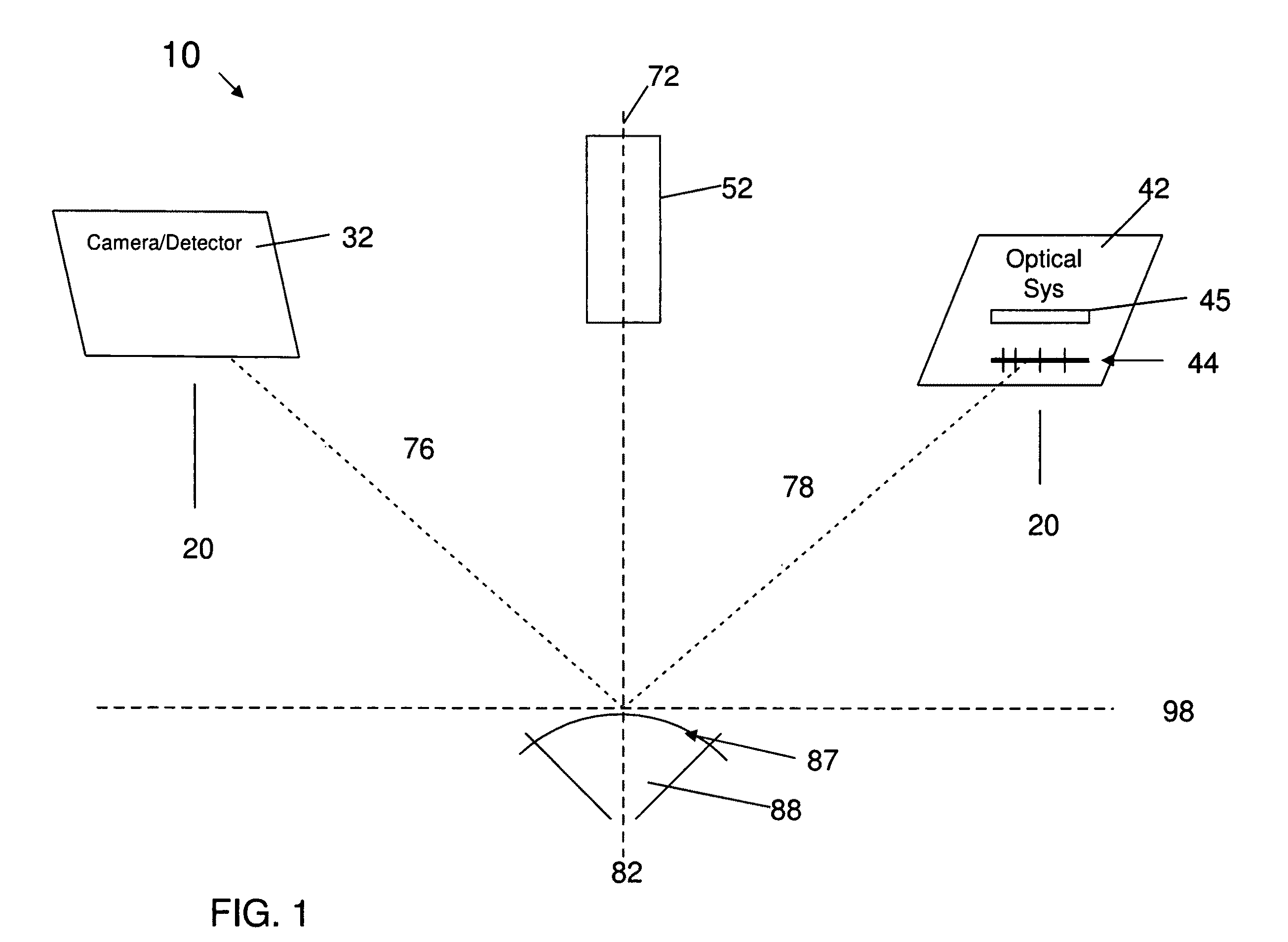
[0065]As shown schematically in FIG. 1, an exemplary embodiment of the invention, referred to as the d.RCT, is a device 10 that enables making topographical deformation characteristic measurements of an in-vivo cornea 87 (of a live eye 88) before and during a deformation interval, and which, therefrom, enables the quantitative determination of biomechanical and biodynamic properties of the in-vivo cornea, that were heretofore unobtainable / indeterminable. The device 10 includes a topographer component 20 and a non-contact surface deformer component 52, that are ‘operationally integrated’ as that term is defined above.

[0066]The non-contact surface deformer component 52, which may be a calibrated air-puff generator or tonometer, is disposed along a first operational axis 72 of the device. The topographer component 20 includes an optical system comprising a camera / detector 32 disposed along a directionally-independent (as that term is defined above) second operational axis 76 of the dev...


PUM


Abstract

Apparatus and methods for measuring a dynamic deformation characteristic of a deformable target surface during a deformation interval. The measurement principles may be applied to a large variety of organic and inorganic materials having a surface that can be deformed by an applied non-contact force. The surface may be light diffusing and non-transparent or non-diffusing and transparent. A device for measuring a dynamic deformation characteristic of an in-vivo cornea during a deformation interval includes a corneal topographer and an air puff generator that are operationally integrated. Use of the inventive device enables a method for making a measurement of a deformation characteristic of the in-vivo cornea during a deformation interval, further allowing a determination of spatially-resolved in-vivo corneal biomechanical and biodynamic properties such as corneal elasticity and corneal viscosity.

Description

RELATED APPLICATION DATA[0001]The instant application is a continuation-in-part of application Ser. No. 12 / 091,307 filed on Apr. 24, 2008, which is a 371 of International application Serial No. PCT / US2006 / 060381 filed on Oct. 31, 2006, which itself claims benefit of U.S. provisional application Ser. No. 60 / 731,756 filed on Oct. 31, 2005. The instant application is also a continuation-in-part of application Ser. No. 11 / 830,372 filed on Jul. 30, 2007, now U.S. Pat. No. 7,866,820 which is a continuation application of Ser. No. 11 / 674,985 filed on Feb. 14, 2007, now abandoned which itself claims priority to provisional application Ser. No. 60 / 773,293 filed on Feb. 14, 2006. The disclosures of all of the foregoing referenced applications are incorporated herein by reference in their entireties.BACKGROUND OF THE INVENTION[0002]1. Field of the Invention[0003]Embodiments of the invention generally relate to methods and apparatus for measuring deformation characteristics of a deformable obje...

Claims


Application Information

Patent Timeline
Patent Type & Authority Patents(United States)
IPC IPC(8): A61B3/10A61B3/16
CPCA61B3/165G01B11/167G01B11/2513G06T7/0057G01N2203/0089G06T7/521
Inventor ROBERTS, CYNTHIA J.MAROUS, JAMES RICHARDMAHMOUD, ASHRAF MOSTAFA
Owner VISION OPTIMIZATION
Learn More