Biologic Vertebral Reconstruction

a vertebral and vertebral technology, applied in the field of biochemical vertebral reconstruction, can solve the problems of reducing the effect of treatment, affecting the recovery of patients, so as to achieve the effect of reducing the extrusion

Active Publication Date: 2009-07-23
SPINAL ELEMENTS INC
View PDF5 Cites 95 Cited by
  • Summary
  • Abstract
  • Description
  • Claims
  • Application Information

AI Technical Summary

Benefits of technology

[0009]Significant aspects of the described embodiments include: (a) the technology involves implantation of a biologic material—artificial bone into the fractured vertebra such that the host bone will replace the artificial bone over a period of time making this a more suitable option than the currently used bone cement; (b) the implant is inserted into the vertebra in a biologically active jacket, to minimize its extrusion into the spinal canal and the paravertebral spaces; (c) because of its biomechanical characteristics, which approximate the host bone, there is relative protection of the neighboring vertebrae against fracture; and (d) the walls of the implant jacket may be impregnated with various substances to achieve various advantageous tasks. Examples of these include bone morphogenic proteins to stimulate incorporation of the artificial bone into the host bone, among others.

Problems solved by technology

As the use of this technique became more common, some adverse effects of the treatment have become apparent.
At the time of surgery, patients may suffer from cardio-respiratory failure associated from infusion of large amounts of polymethylmethacrylate monomers into the circulation; in the case of vertebroplasty which requires injection of the cement at high pressures, extrusion of the cement into the venous channels and embolization into the pulmonary veins have been described; the cement may extrude through the cracks in the vertebrae into the spinal canal and compress the spinal cord or the spinal nerves with possible serious complications.
However, the biomechanical alterations caused even by an apparently minor deformity may lead to the development of chronic back pain.

Method used


Image

  • Biologic Vertebral Reconstruction
  • Biologic Vertebral Reconstruction
  • Biologic Vertebral Reconstruction

Examples


Embodiment Construction

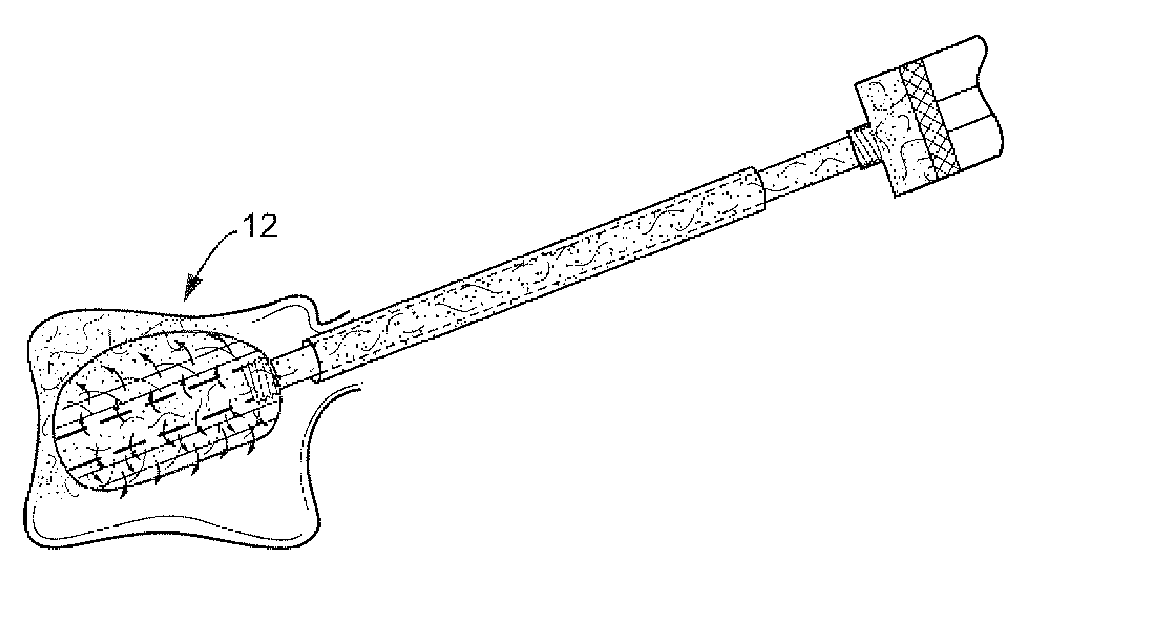
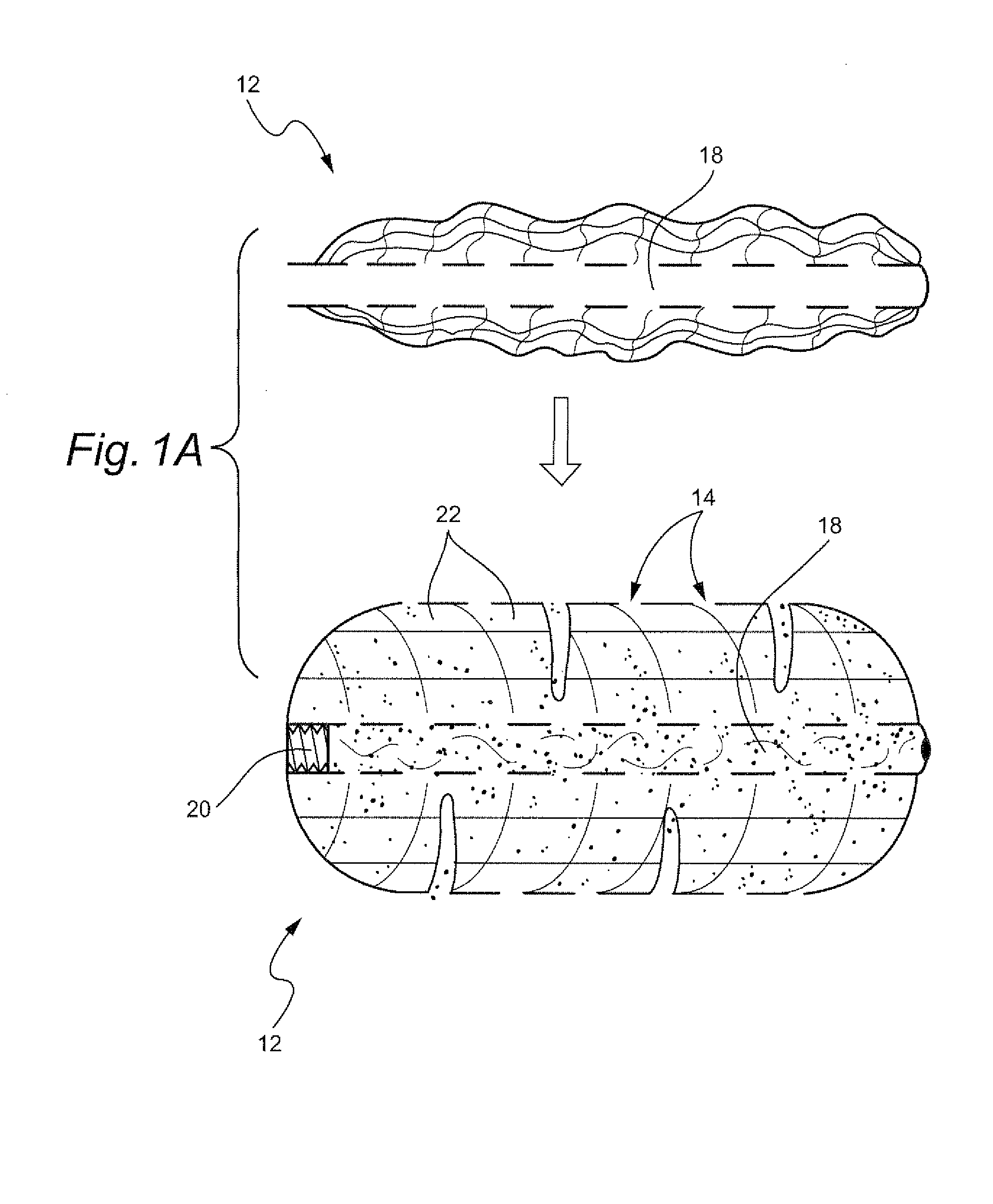
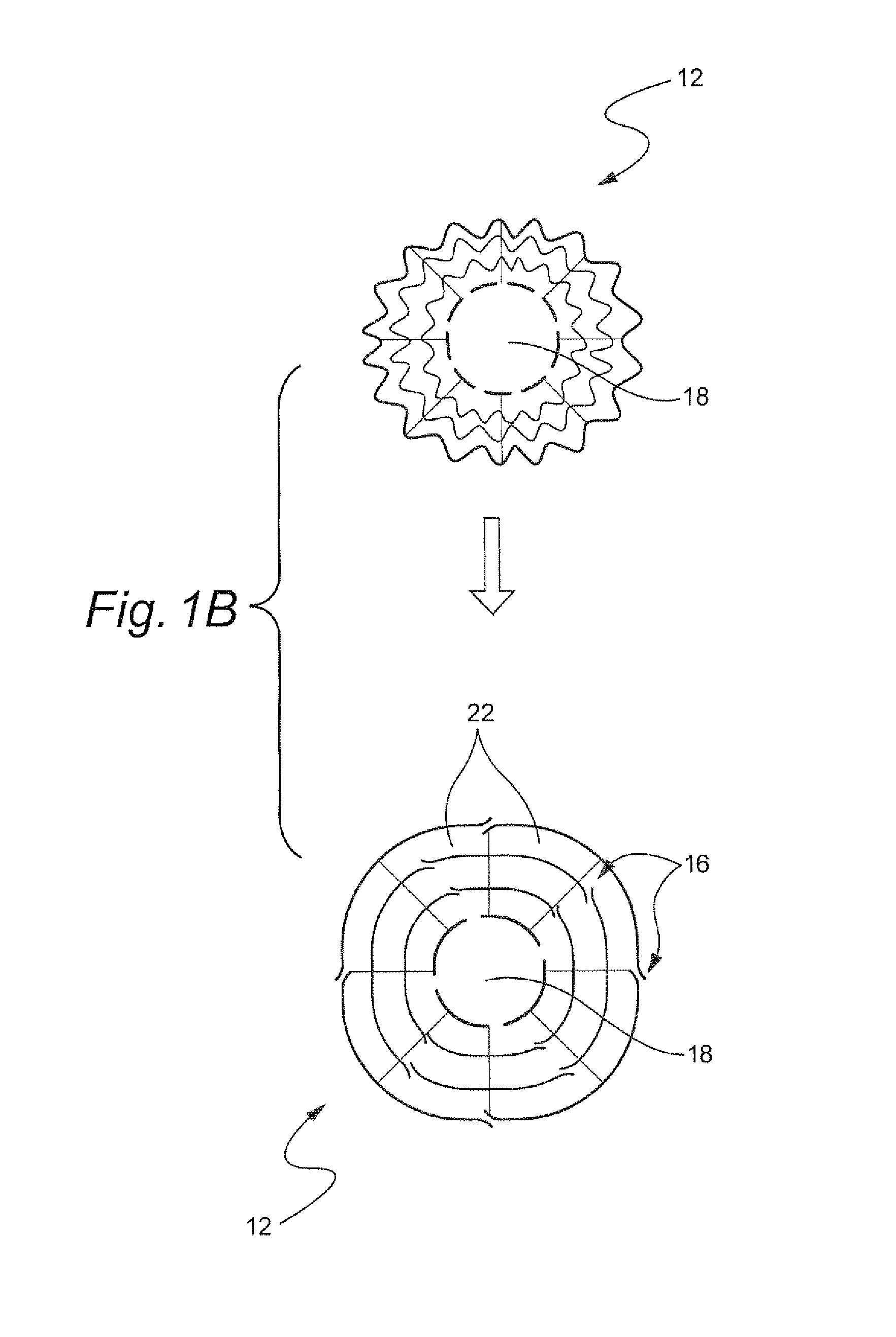
[0022]With reference to FIGS. 1A and 1B, a preferred embodiment includes a jacket 12 of synthetic bio-absorbable fiber network woven like cloth and may be uni-compartmental or multi-loculated. If multi-loculated the loculations 14 will have connecting valves 16 made of overlapping wall fibers acting as trap-doors that open up as the chamber is filled with artificial bone to allow filling of the neighboring chambers. The jacket 12 has a central fenestrated channel 18 that runs through the length of the jacket 12. The channel 18 is sealed at its far end, and the near end is threaded 20 to allow a cement injector to be screwed on.

[0023]The multi-loculated design has concentric chambers with the central channel 18 running down the center of the innermost chamber. Each chamber may be partially loculated to reinforce the construct with multiple networks of fibers to minimize the risk of compression fracture of the implant itself. The artificial bone is injected into the central channel 18...


PUM


Abstract

A device and method for biologic vertebral reconstruction utilizes a biologically active jacket inserted into a cavity formed in a vertebra to be reconstructed. An artificial bone material is inserted into the biologically active jacket and allowed to set. The structure and method described herein provide for effective biologic vertebral reconstruction. The use of a biological material and artificial bone enables the host bone to replace the artificial bone over a period of time. Additionally, the structure of the biologically active jacket minimizes any impact into the spinal canal and the paravertebral spaces. Moreover, because of its biomechanical characteristics, which approximate the host bone, there is relative protection of the neighboring vertebral against fracture. Still further, the materials of the biologically active jacket may be impregnated with various substances to achieve various advantageous tasks.

Description

CROSS-REFERENCES TO RELATED APPLICATIONS[0001](NOT APPLICABLE)STATEMENT REGARDING FEDERALLY SPONSORED RESEARCH OR DEVELOPMENT[0002](NOT APPLICABLE)BACKGROUND OF THE INVENTION[0003]The invention relates to biologic vertebral reconstruction and, more particularly, to devices and methods for biologic vertebral reconstruction utilizing a biologically active jacket inserted into a cavity formed in a vertebra to be reconstructed.[0004]Vertebral compression fractures are quite common in the elderly population. These fractures occur following minor injuries or spontaneously in the elderly osteoporotic spine. The other group of patients, usually middle aged, is those on long term steroid therapy for conditions such as chronic obstructive pulmonary disease. In the younger population with normal bone mineralization, vertebral fractures usually occur following high energy injuries such as motor vehicle accidents or a fall from heights.[0005]Until recently, the elderly osteoporotic fractures wer...

Claims


Application Information

Patent Timeline
Patent Type & Authority Applications(United States)
IPC IPC(8): A61F2/44A61B17/58
CPCA61B17/7097A61F2/2846A61F2/44A61F2002/2817A61L27/54
Inventor OSMAN, SAID G.
Owner SPINAL ELEMENTS INC
Why Eureka
Try Eureka