Seal assembly

a technology of diaphragm and seal assembly, which is applied in the direction of diaphragm valves, engine seals, valve arrangements, etc., can solve the problems of elastomeric body may be exposed to relatively harsh fluid composition, fluid temperature and/or fluid pressure, and may be subject to variable tightening forces and extrusion forces, etc., and the system may be prone to system failure, and the cost of labor and parts

Active Publication Date: 2012-08-09
PARKER INTANGIBLES LLC
View PDF13 Cites 8 Cited by
  • Summary
  • Abstract
  • Description
  • Claims
  • Application Information

AI Technical Summary

Benefits of technology

[0012]The carrier lateral surface of the preferred embodiment may also include laterally extending openings between adjacent ones of the towers. The stationary portion of the elastomeric body may extend into the openings and may be discontinuous at the location of each of said towers. The film may cover the tower lateral control surfaces, as well as the elastomeric body, to provide a smooth continuous uninterrupted working surface for the seal assembly.
[0013]According to the preferred embodiment, the body may be a thermosetting material and the film may be a thermoplastic material. The thickness of the film measured in a direction perpendicular to

Problems solved by technology

The elastomeric body of such diaphragm seal assemblies may be exposed to relatively harsh conditions of fluid composition, fluid temperature and/or fluid pressure.
Still further, the elastomeric body may be exposed to variable tightening forces and to extrusion forces during insta

Method used


Image

  • Seal assembly
  • Seal assembly
  • Seal assembly

Examples


Embodiment Construction

[0027]The principles, embodiments and operation of the present invention are shown in the accompanying drawings and described in detail herein. These drawings and this description are not to be construed as being limited to the particular illustrative forms of the invention disclosed. It will thus become apparent to those skilled in the art that various modifications of the embodiments herein can be made without departing from the spirit or scope of the invention.

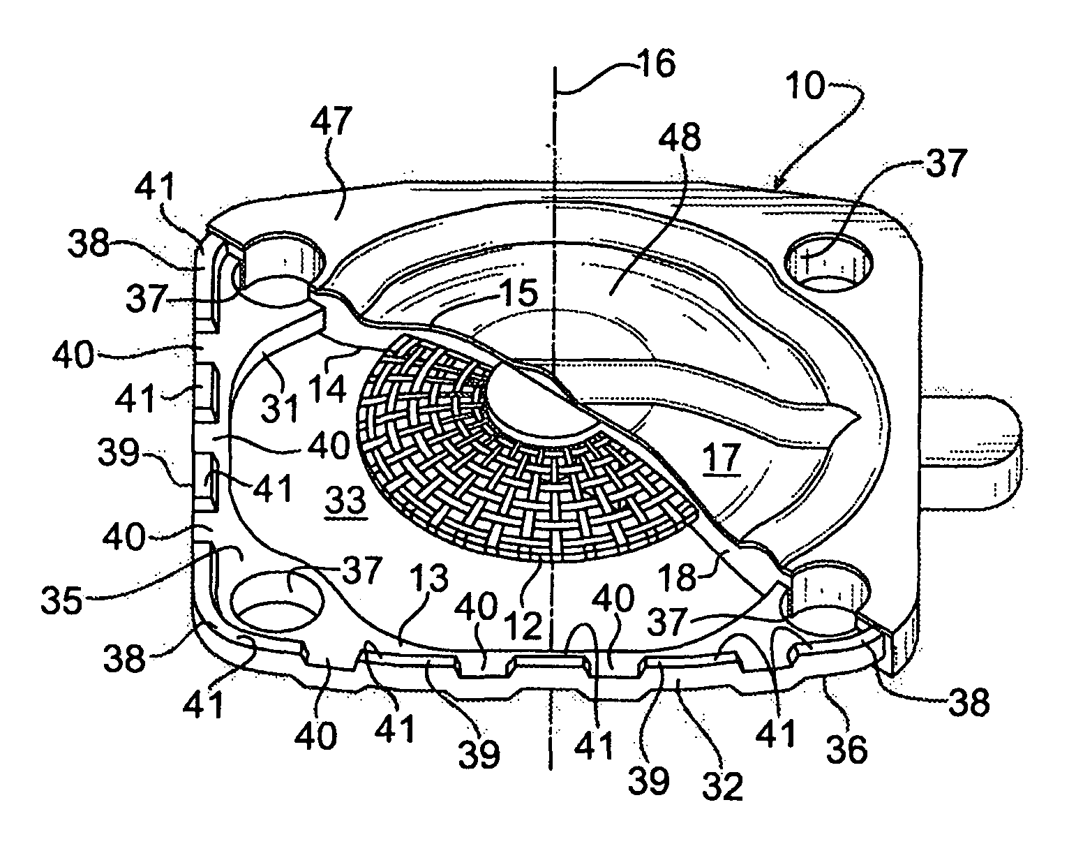
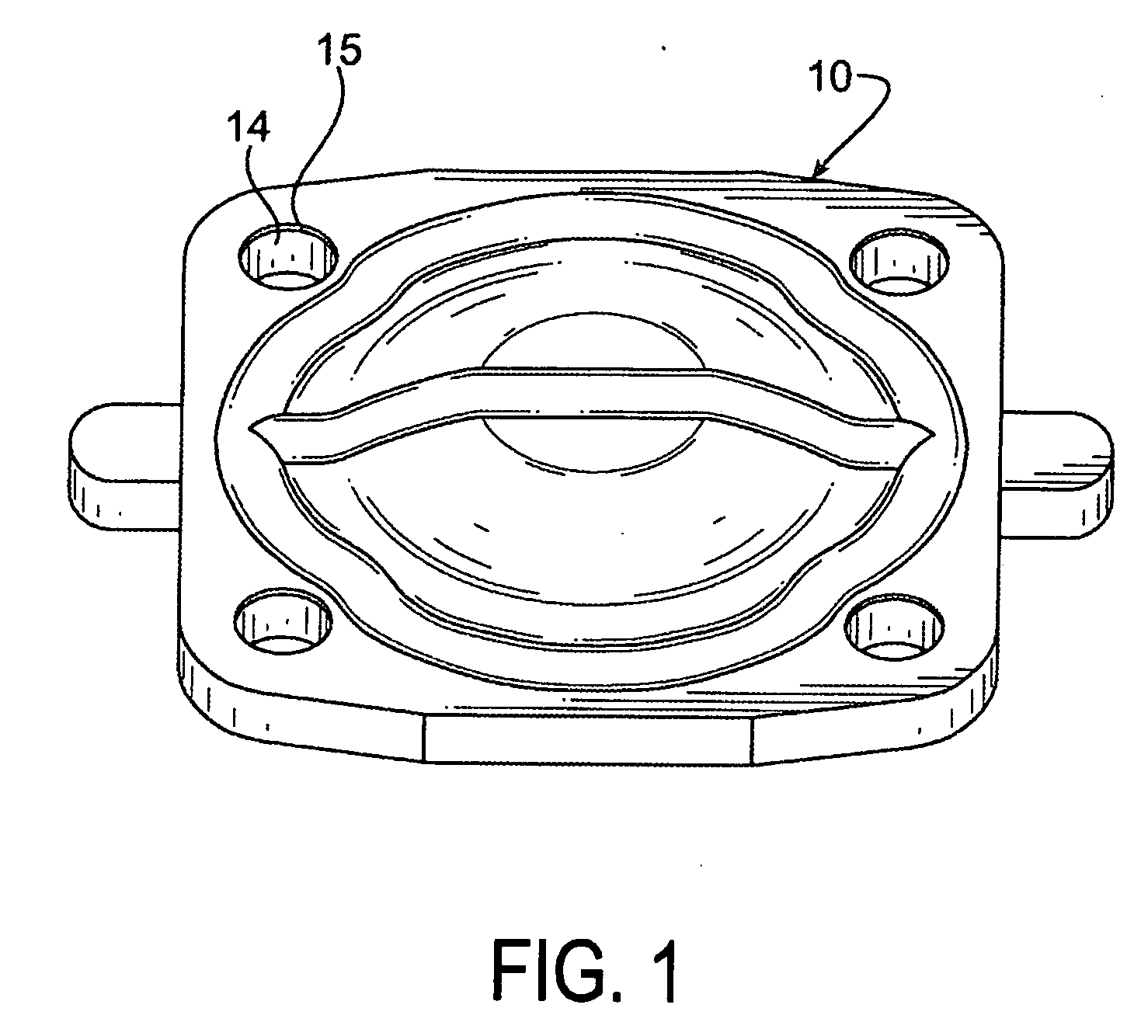
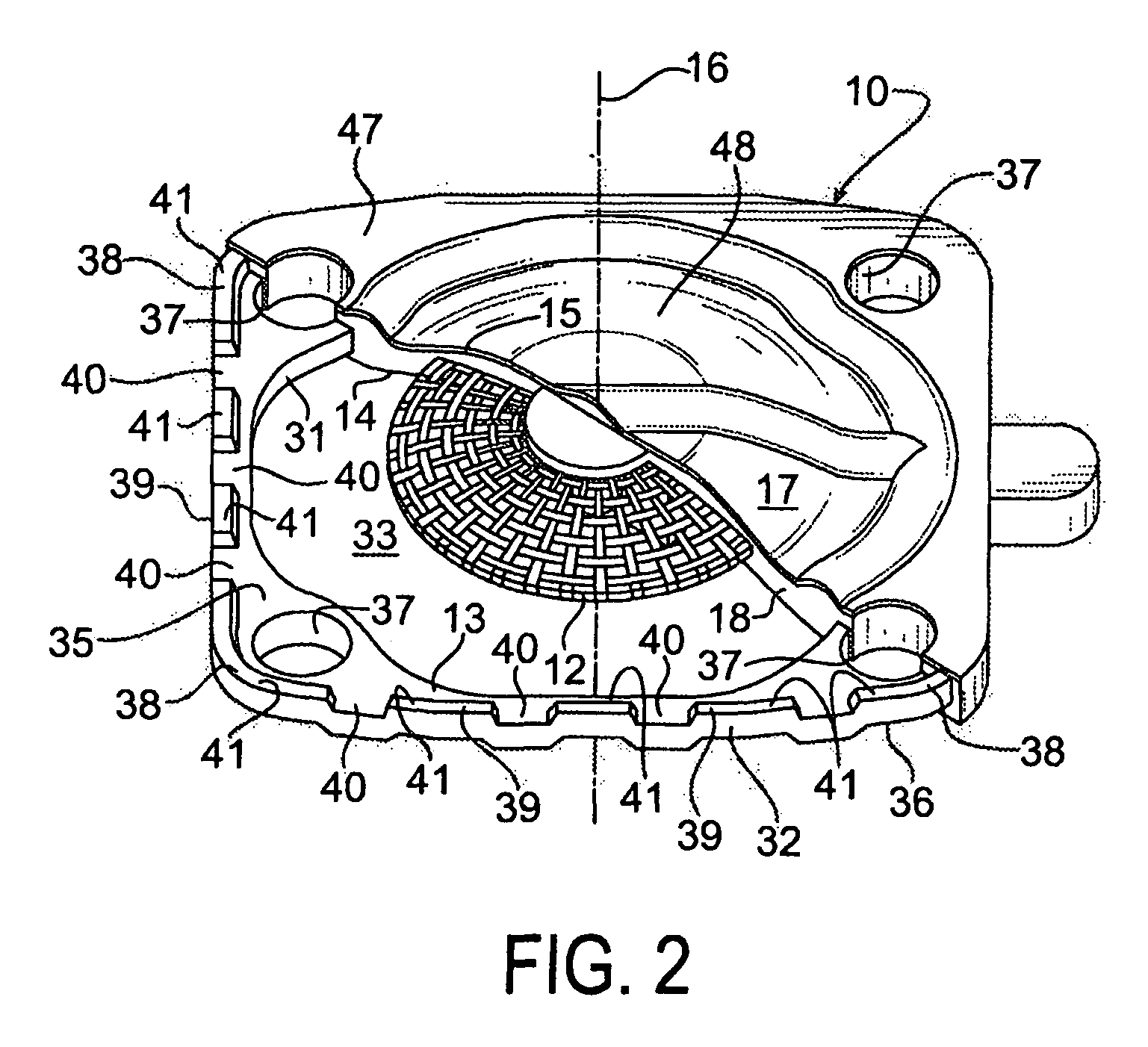
[0028]Referring now to FIGS. 1 and 2, a diaphragm seal assembly 10 according to one preferred embodiment of this invention is illustrated. The diaphragm seal assembly 10 includes an attachment stud 11, a reinforcing mesh 12, a rigid carrier 13, an elastomeric body 14, and an elastomeric film 15. The attachment stud 11, reinforcing mesh 12, rigid carrier 13, elastomeric body 14 and elastomeric film 15 are each coaxially arranged about a longitudinal axis 16. As also further described below, the diaphragm seal assembly 10 inc...


PUM


Abstract

A seal assembly 10 includes an attachment stud 11, a reinforcing mesh 12, a rigid carrier 13, an elastomeric body 14, and an elastomeric film 15, each having a longitudinal axis 16. The carrier 13 includes an inner peripheral surface 31 defining a central opening 33 and an outer peripheral surface 32. A lateral surface 35 of the carrier 13 extends between the peripheral surfaces. Corner towers 38 and intermediate towers 39 are arranged along the outer peripheral surface 32. The towers are spaced apart by openings 40 and terminate in control surfaces 41. The body 14 includes a stationary portion 47 generally aligned with the carrier 13 and a diaphragm portion 48 generally aligned with the opening 33. The film 15 extends over and is bonded to the body portion 14 and the towers 38, 39 to provide a smooth uninterrupted chemically resistant surface for the seal assembly 10.

Description

CROSS REFERENCE TO RELATED APPLICATIONS[0001]The present application claims the benefit of the filing date of U.S. Provisional Patent Application Ser. No. 61252850 filed Oct. 19, 2009, the disclosure of which is incorporated herein by reference in its entirety.TECHNICAL FIELD[0002]This invention relates generally to seal assemblies. More particularly, this invention relates to a diaphragm seal assembly for use in a fluid control valve.BACKGROUND OF THE INVENTION[0003]Diaphragm seal assemblies are widely used in fluid control valves to control the flow of a wide variety of fluids through the valve at various conditions of temperature, pressure and other conditions. Such diaphragm seal assemblies typically include an elastomeric body. A stationary peripheral portion of the elastomeric body may be secured to a housing of the fluid control valve, and a diaphragm portion of the elastomeric body may be carried by the stationary peripheral portion for movement between a closed or sealed po...

Claims


Application Information

Patent Timeline
IPC IPC(8): F16J15/10
CPCF16J15/10F16K7/12
Inventor GOULDING, NIGEL S.
Owner PARKER INTANGIBLES LLC
Why Eureka
Try Eureka