
Graphic recognition device, graphic recognition method, and graphic recognition program

a graphic recognition and program technology, applied in image analysis, image enhancement, instruments, etc., can solve the problems of flag recognition process robustness, process is not performed, information on shadow area cannot be applied to flag recognition process,

Inactive Publication Date: 2012-07-24
NEC CORP
View PDF5 Cites 3 Cited by
  • Summary
  • Abstract
  • Description
  • Claims
  • Application Information

AI Technical Summary

Benefits of technology

Enables robust flag recognition that is not influenced by shadow areas, improving recognition accuracy by distinguishing and processing both shadow and non-shadow regions within images, thus enhancing the reliability of flag detection in various lighting conditions.

Problems solved by technology

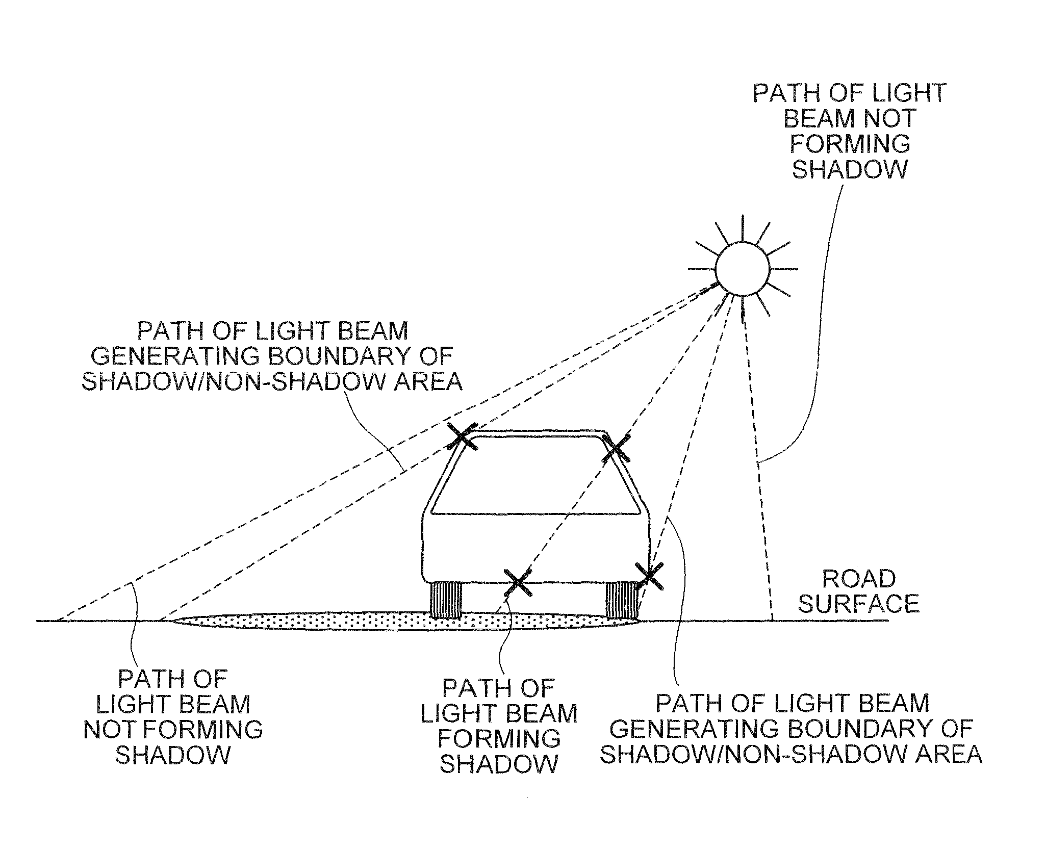
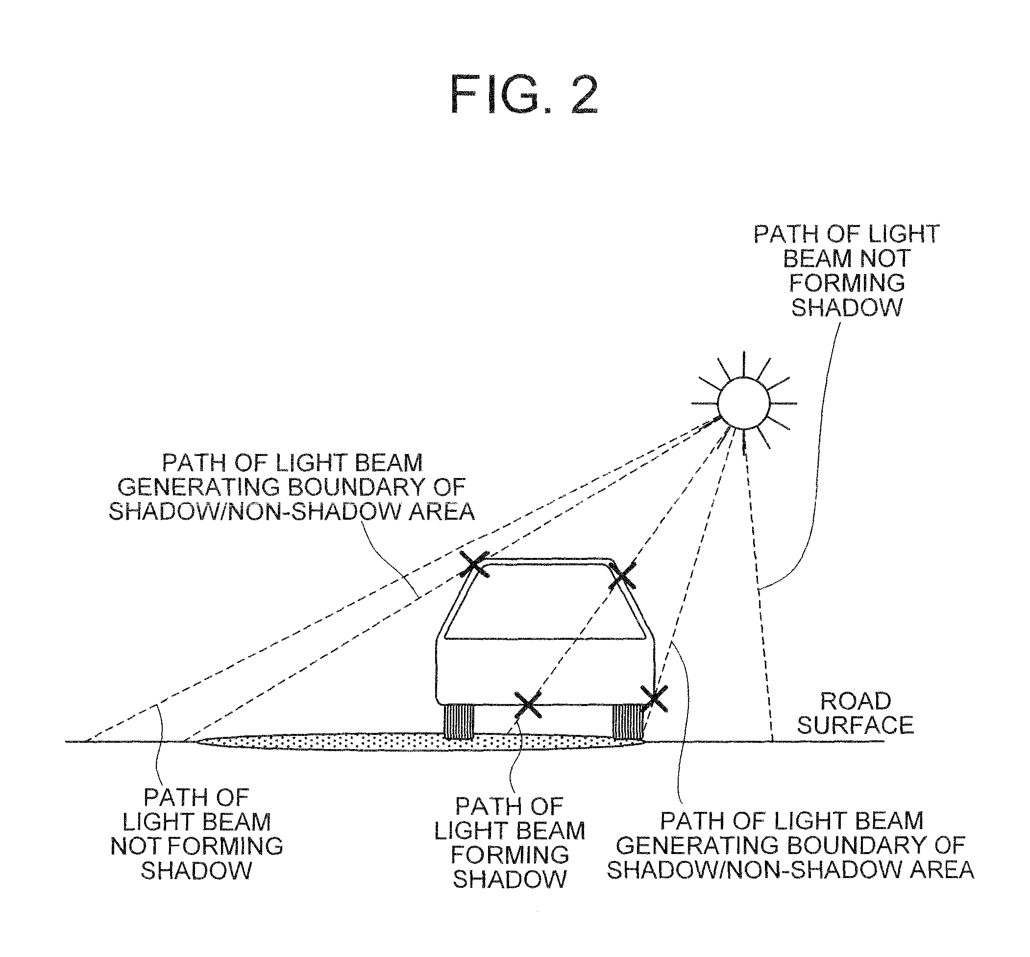
However, in the system disclosed in patent document 1, the location of the sun is calculated, but the shadow area generated by the object is not specified, and thus information on the shadow area cannot be applied to the flag recognition process.
Moreover, the recognition process is not performed after specifying the shadow area, and a flag recognition robust to the influence of the shadow area is not realized.

Method used


Image

  • Graphic recognition device, graphic recognition method, and graphic recognition program
  • Graphic recognition device, graphic recognition method, and graphic recognition program
  • Graphic recognition device, graphic recognition method, and graphic recognition program

Examples


first exemplary embodiment

[First Exemplary Embodiment]

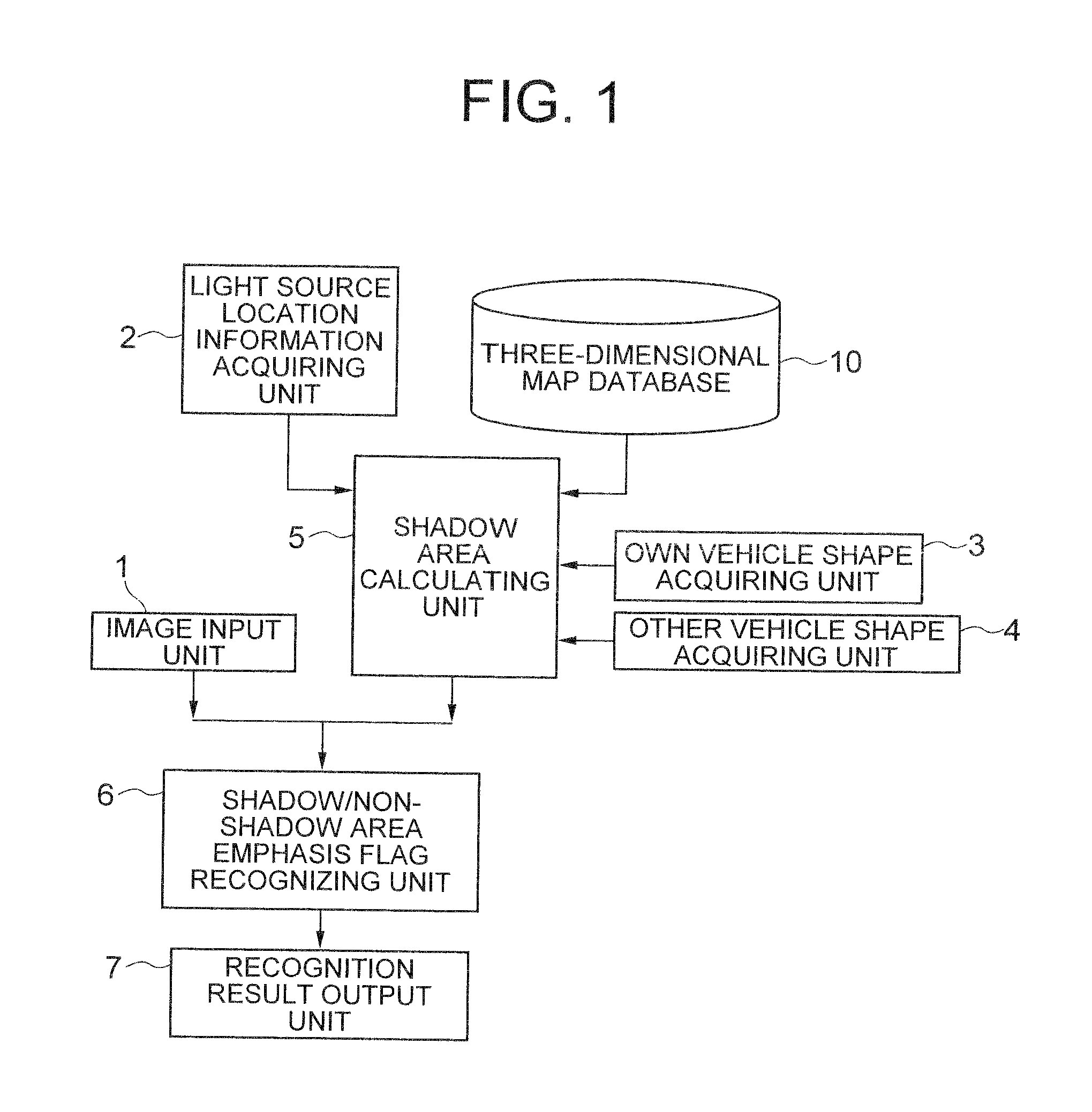
[0050]FIG. 1 is a block diagram showing a configuration of a graphic recognition device of a first exemplary embodiment of the present invention. The graphic recognition device includes an image input unit 1, a light source location information acquiring unit 2, an own vehicle shape acquiring unit 3, other vehicle shape acquiring unit 4, a shadow area calculating unit 5, a shadow / non-shadow area emphasis flag recognizing unit 6, a recognition result output unit 7, and a three-dimensional map database 10.

[0051]The image input unit 1 inputs the image of the outside environment of a vehicle photographed with a vehicle exterior photographic camera (photographic device) mounted on the own vehicle. The image input unit 1 inputs the image of the outside environment of a vehicle photographed with the in-vehicle camera, converts the same to a digital image, and outputs to the shadow / non-shadow area emphasis flag recognizing unit 6.

[0052]The light source location i...

second exemplary embodiment

[Second Exemplary Embodiment]

[0087]A second exemplary embodiment of the invention will now be described with reference to the drawings.

[0088]FIG. 5 is a block diagram showing a configuration of a graphic recognition device of the second exemplary embodiment of the invention. The graphic recognition device of the second exemplary embodiment calculates the location information of the light source from the location of the own vehicle, the location of the other vehicle, and the three-dimensional map database.

[0089]The light source location information acquiring unit 2 calculates the location of the light source with the own vehicle shape information obtained from the own vehicle shape acquiring unit 3, the other vehicle shape information and the location information of the other vehicle obtained from the other vehicle shape acquiring unit 4, and the object shape information stored in the three-dimensional map database 10 as inputs. As shown in FIG. 5, the second exemplary embodiment dif...

third exemplary embodiment

[Third Exemplary Embodiment]

[0096]Next, a third exemplary embodiment of the invention will be described with reference to the drawings.

[0097]FIG. 6 is a block diagram showing a configuration of a graphic recognition device of the third exemplary embodiment of the invention. In the third exemplary embodiment, if the light source location is not accurately known, a plurality of locations is set for the light source location according to a rule defined in advance, and the shadow area calculated from each set location and the actually photographed image are compared to select the shadow area that matches the most.

[0098]FIG. 7 is an explanatory view showing one example of a method in which a light source location information acquiring unit 8 shown in FIG. 6 sets a plurality of virtual light sources (virtual sun) as candidates.

[0099]The light source location information acquiring unit 8 sets a plurality of virtual suns, and outputs the three-dimensional coordinate data indicating the resp...


PUM


Abstract

A graphic recognition device, method, and recognition program recognize graphics without being influenced by an image shadow area. Image input unit acquires the image of the outside environment of a vehicle using a vehicle mounted camera. A light source location information acquiring unit calculates location of a light source such as the sun using the acquired image. User vehicle shape acquiring unit and other vehicle shape acquiring unit generate shape information for the vehicles indicating the location of points forming vehicle contours. Shadow area calculating unit calculates, on the basis of both vehicles' shape information, the object shape information and the light source location information, the location coordinates of the shadow area, and converts the location coordinates into two-dimensional coordinates to the shadow / non-shadow area emphasis flag recognizing unit, which recognizes the flag in the image by judging the presence / absence of the recognition object in each shadow and non-shadow area specified.

Description

TECHNICAL FIELD[0001]The present invention relates to graphic recognition devices for recognizing graphics in an image, flag recognition methods, and flag recognition programs, in particular, to a graphic recognition device for recognizing a flag in an image photographed by an in-vehicle camera, a flag recognition method, and a flag recognition program.BACKGROUND ART[0002]Most traffic accidents by automobiles are caused by the oversight of the driver due to the presence of blind corner or lack of attention. It is important for the drivers to accurately recognize road signs such as “stop”, or road information related to safety such as road surface sign indicating crossing, stop line, speed limit, and the like for safe driving. As a technique of recognizing the surrounding signs and notifying the same to the driver, a method of establishing a communication between the road surface and the vehicle, a method of performing pattern recognition on the image acquired by the vehicle exterior...

Claims


Application Information

Patent Timeline
Patent Type & Authority Patents(United States)
IPC IPC(8): G06K9/00G06V10/145
CPCG06K9/2036G06T7/0081G06K9/00805G06T2207/20144G06T2207/30252G06T2207/20012G06T7/11G06T7/194G06V20/58G06V10/145
Inventor MIYAMOTO, SHINICHI
Owner NEC CORP
Learn More